
Temperature Sensors: RTD, Thermocouple, Thermistor & Selection
Industrial temperature sensors commonly use an RTD, thermocouple, thermistor or semiconductor element. RTDs favour accuracy and stability, thermocouples cover demanding and high-temperature service, thermistors give high sensitivity over narrower ranges, and semiconductor sensors suit electronic or equipment-level measurement.
Select the sensor from the required temperature range, accuracy and stability, response time, process connection, vibration and chemical exposure, installation geometry, and the electrical interface required by the receiving system.
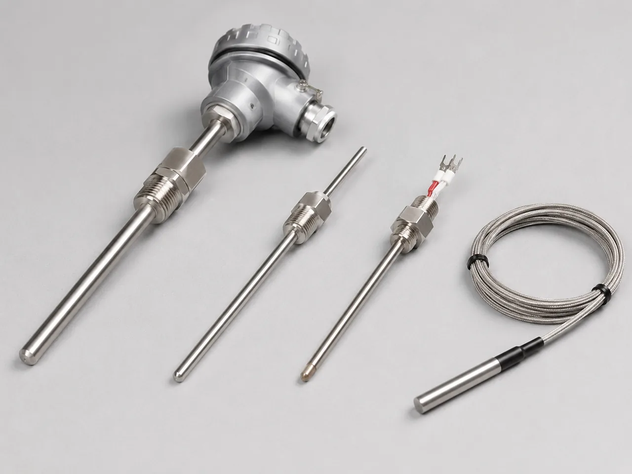
Choose the sensing element and the mechanical assembly separately. A good Pt100 can still measure poorly if the probe is too shallow, badly coupled, exposed to stem conduction error or installed in a thermowell with excessive thermal lag.
RTD, thermocouple, thermistor or semiconductor sensor?
Temperature range is only one part of the choice. The sensor types also differ in signal level, linearity, stability, wiring, ruggedness and installation practice. Probe construction and mounting can affect the measurement as much as the sensing element itself.
| Type | What changes with temperature | Typical strengths | Main limitations |
|---|---|---|---|
| Platinum RTD | Electrical resistance of a platinum element. | Good accuracy, repeatability and long-term stability; standardised Pt100/Pt1000 characteristics. | Lead resistance must be handled correctly; generally less suited than thermocouples to extreme temperature and severe vibration. |
| Thermocouple | Thermoelectric EMF produced by dissimilar conductors and junction temperatures. | Wide usable temperature range, small sensing junctions, rugged constructions and fast response options. | Low-level nonlinear signal, cold-junction compensation and correct thermocouple/extension materials are required. |
| Thermistor | Strongly temperature-dependent semiconductor resistance. | High sensitivity and compact size over a designed operating range. | Nonlinear response, narrower practical range and possible self-heating from measurement current. |
| Semiconductor / IC | Electronic device behaviour converted to analogue or digital output. | Easy integration, factory calibration and direct digital interfaces in equipment or embedded systems. | Temperature and environmental limits are set by the electronics and package, so they are not a direct replacement for every process probe. |
How does an RTD measure temperature?
An RTD measures temperature from the predictable change in resistance of a metal element, most often platinum. A Pt100 has a nominal resistance of 100 Ω at 0 °C; a Pt1000 has 1000 Ω at 0 °C. The higher nominal resistance of a Pt1000 makes a given lead resistance a smaller percentage of the measurement.
For the common industrial platinum characteristic, α is approximately 0.00385 Ω/Ω/°C. The sensor input applies a small excitation current, measures resistance and converts the result to temperature. Excessive excitation current can warm the element and create self-heating error.
Platinum RTDs are commonly made as wire-wound or thin-film elements. Construction affects usable temperature range, vibration behaviour, response and long-term stability even when two sensors follow the same Pt100 or Pt1000 resistance curve.
2-wire, 3-wire and 4-wire RTD connections
A 2-wire RTD includes both lead resistances in the measurement. A 3-wire input compensates lead resistance when the matched leads and measurement circuit satisfy its assumptions. A 4-wire Kelvin connection separates excitation and voltage sensing, giving the best rejection of lead-resistance error.
How does a thermocouple measure temperature?
A thermocouple uses two dissimilar conductors and produces a thermoelectric EMF related to the temperature difference between the measuring junction and the reference junction. The instrument therefore needs the reference-junction temperature at its thermocouple terminals; this is the purpose of cold-junction compensation (CJC).
Common base-metal types
K is widely used for general industrial service. J is used over moderate temperature ranges, but its iron conductor limits suitability in oxidising or moist high-temperature environments. T is useful at low temperatures. E provides relatively high thermoelectric sensitivity. N is chosen for elevated-temperature service where better thermoelectric stability than Type K is useful.
Noble-metal types
R, S and B thermocouples use platinum-group alloys for high-temperature measurement. Selection depends on atmosphere, temperature, sheath or protection tube and required tolerance.
Cold-junction compensation
Where do thermistors and semiconductor temperature sensors fit?
NTC thermistors decrease in resistance as temperature rises, while PTC devices increase resistance over their intended operating region. Their resistance change can be large, which gives high sensitivity, but the response is nonlinear and the measurement current must be low enough to avoid significant self-heating.
Integrated semiconductor sensors can provide a conditioned analogue voltage/current or a digital interface. They are common inside electronics, drives, motors, battery systems, HVAC equipment and machinery when the specified temperature range, package and environmental ratings suit the application. They should not be confused with a process transmitter built around an RTD or thermocouple input.
Probe installation can dominate the measurement error
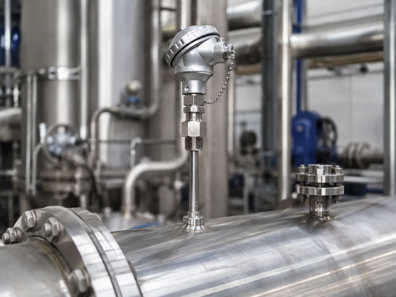
Temperature is measured at the sensing element, not at the process in general. The probe therefore needs good thermal coupling to the material whose temperature matters. Poor immersion, air gaps, conductive heat loss along the stem, radiation, surface mounting and nearby hot or cold structures can all bias the reading.
| Installation factor | Why it matters |
|---|---|
| Immersion depth | Too little insertion can let heat conducted through the stem and connection dominate the sensor temperature. Required depth depends on probe and thermowell design, process, flow and temperature difference. |
| Thermowell | Protects the sensor and allows replacement without opening the process, but adds thermal mass and can slow response. Mechanical design must suit pressure, flow and vibration. |
| Thermal contact | An insert that does not contact the thermowell tip or has a large air gap responds more slowly and can read differently from the process. |
| Sheath / materials | Material, diameter and wall thickness affect corrosion resistance, mechanical strength and response time. |
| Connection head | Ambient heat, moisture and vibration at the head can affect terminals, transmitter electronics and cold-junction compensation. |
Raw temperature sensors and temperature transmitters are different devices
A raw RTD presents resistance. A raw thermocouple presents a small thermoelectric voltage. Neither is automatically a 4–20 mA device. A head-mounted, DIN-rail or field transmitter can accept the sensor signal, perform linearisation and diagnostics, and then provide a standard industrial output.
Direct sensor input
- PLC or instrument must support the exact RTD or thermocouple type.
- RTD input must match 2-, 3- or 4-wire configuration.
- Thermocouple input must support the type and cold-junction compensation.
- Low-level wiring is more exposed to lead and interference effects.
Temperature transmitter
- Converts the raw sensor to a standard field signal.
- Can detect supported sensor faults and convert a configured temperature range to a standard output.
- Allows long-distance transmission using 4–20 mA or a supported digital interface.
- Transmitter accuracy, ambient temperature and configuration become part of the measurement chain.
How do you choose an industrial temperature sensor?
Choose the required temperature range first, then define the accuracy, stability and response requirements. Match the probe, sheath, process connection and thermowell to the process, then choose RTD, thermocouple or another element and an electrical interface that the receiving system can measure correctly.
- Define the real temperature range. Include normal operation, startup, cleaning, sterilisation, upset conditions and ambient temperature at the connection head.
- Set the performance requirements. Separate accuracy, repeatability, long-term drift, resolution and response time instead of treating them as one specification.
- Choose the sensing technology. Prefer an RTD where stability and accuracy at moderate temperatures dominate; consider a thermocouple where temperature, ruggedness or response pushes beyond the practical RTD assembly.
- Design the mechanical installation. Select probe diameter, sheath, process connection, insertion length, thermowell and materials for the process and maintenance plan.
- Match the electrical interface. Confirm RTD wire configuration, thermocouple type/CJC, transmitter input and output, isolation and PLC or instrument compatibility.
- Check dynamic performance. A thick thermowell can make a fast sensing element respond slowly; verify the complete assembly rather than the bare-element response.
- Plan calibration and replacement. Decide whether the sensor can be removed, checked or replaced without disturbing the process and how the transmitter configuration will be controlled.
Troubleshooting temperature measurement errors
Separate the problem into the sensing element, wiring, transmitter/input and mechanical installation. A stable electrical reading can still be the wrong process temperature if the probe is poorly located or thermally coupled.
| Symptom | Checks |
|---|---|
| RTD reads consistently high | 2-wire lead resistance, wrong Pt100/Pt1000 selection, incorrect α/curve, transmitter range or calibration offset. |
| RTD reading is unstable | Intermittent leads, moisture ingress, poor terminal contact, EMI, mismatched 3-wire leads or excessive excitation/self-heating. |
| Thermocouple reads the wrong temperature | Wrong thermocouple type, reversed polarity, incorrect extension/compensating cable, bad CJC, extra dissimilar-metal junctions or damaged sensor. |
| Reading is slow | Large sheath or thermowell, air gap, poor contact at the tip, low process velocity, protective coatings or installation away from the real thermal zone. |
| Reading differs from a nearby reference | Do not assume both points are at the same temperature. Compare immersion, location, thermal gradients, response time, calibration and mounting. |
| Transmitter shows sensor break | Open RTD/thermocouple, loose terminal, wrong wiring mode, failed lead, incompatible input configuration or transmitter sensor-break setting. |