
Pressure Sensors: Gauge, Absolute, Differential & Selection
A pressure sensor converts pressure acting on a diaphragm or sensing element into an electrical signal. Industrial devices measure gauge pressure relative to atmosphere, absolute pressure relative to vacuum, or differential pressure between two process points.
Choose the reference type and pressure range first, then check accuracy over temperature, overpressure and burst limits, wetted materials, process connection, dynamic pressure behaviour, electrical output and installation conditions.
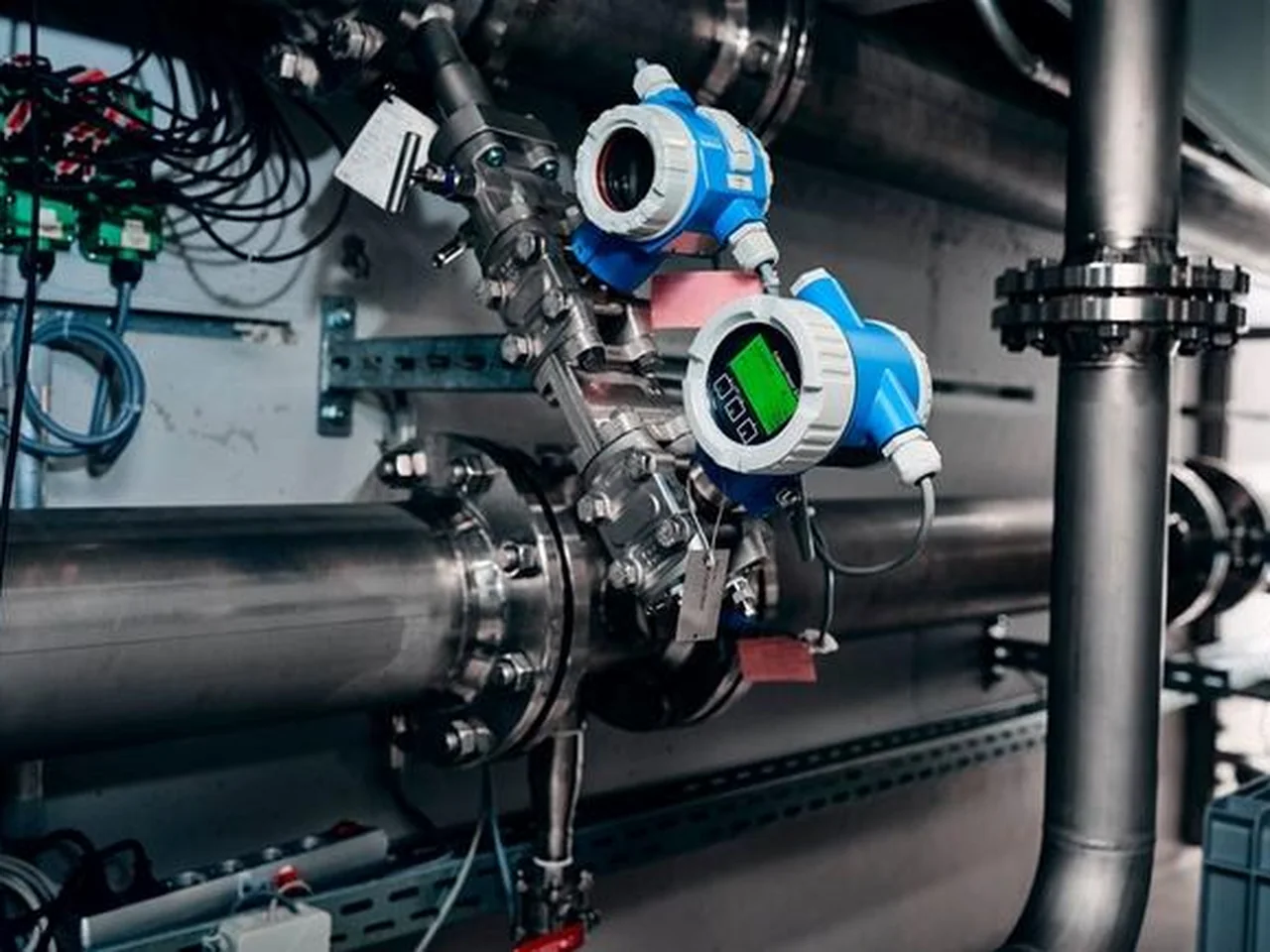
A 0–10 bar gauge sensor and a 0–10 bar absolute sensor do not measure the same quantity. The reference pressure is part of the specification, not a label that can be ignored during replacement.
Pressure sensor types: gauge, absolute and differential
Gauge pressure is measured relative to local atmospheric pressure. Absolute pressure is measured from an absolute-vacuum reference. Differential pressure is the difference between two applied pressures. A sensor must use the reference that matches the physical quantity required by the control or measurement system.
| Pressure type | Reference | Common uses | Important point |
|---|---|---|---|
| Gauge pressure | Local atmosphere | Hydraulics, pneumatics, pumps, compressed air, many process lines. | A vented reference follows atmospheric pressure; blocked or contaminated vents can shift the reading. |
| Absolute pressure | Sealed vacuum reference | Vacuum measurement, barometric measurement, gas calculations and processes where atmospheric variation must not enter the result. | Zero absolute pressure is absolute vacuum, not local atmosphere. |
| Differential pressure | Second process pressure | Filter condition, flow across a primary element, closed-vessel level and pressure-drop measurement. | The differential range and the allowable static line pressure are separate limits. |
How does an electronic pressure sensor work?
Process pressure deflects a diaphragm or another elastic element. The sensor converts that small mechanical deformation into an electrical quantity, then electronics compensate, linearise and scale the signal. The measuring cell may be exposed directly to the medium or isolated from it by a process diaphragm and fill fluid.
Piezoelectric pressure sensors are used primarily for dynamic or rapidly changing pressure, including pulsation, combustion and impact measurements. Conventional piezoelectric elements are not the normal choice for long-term static process pressure measurement.
Transmitter performance also depends on diaphragm material, fill fluid where used, mechanical construction, temperature compensation, electronics and calibration.
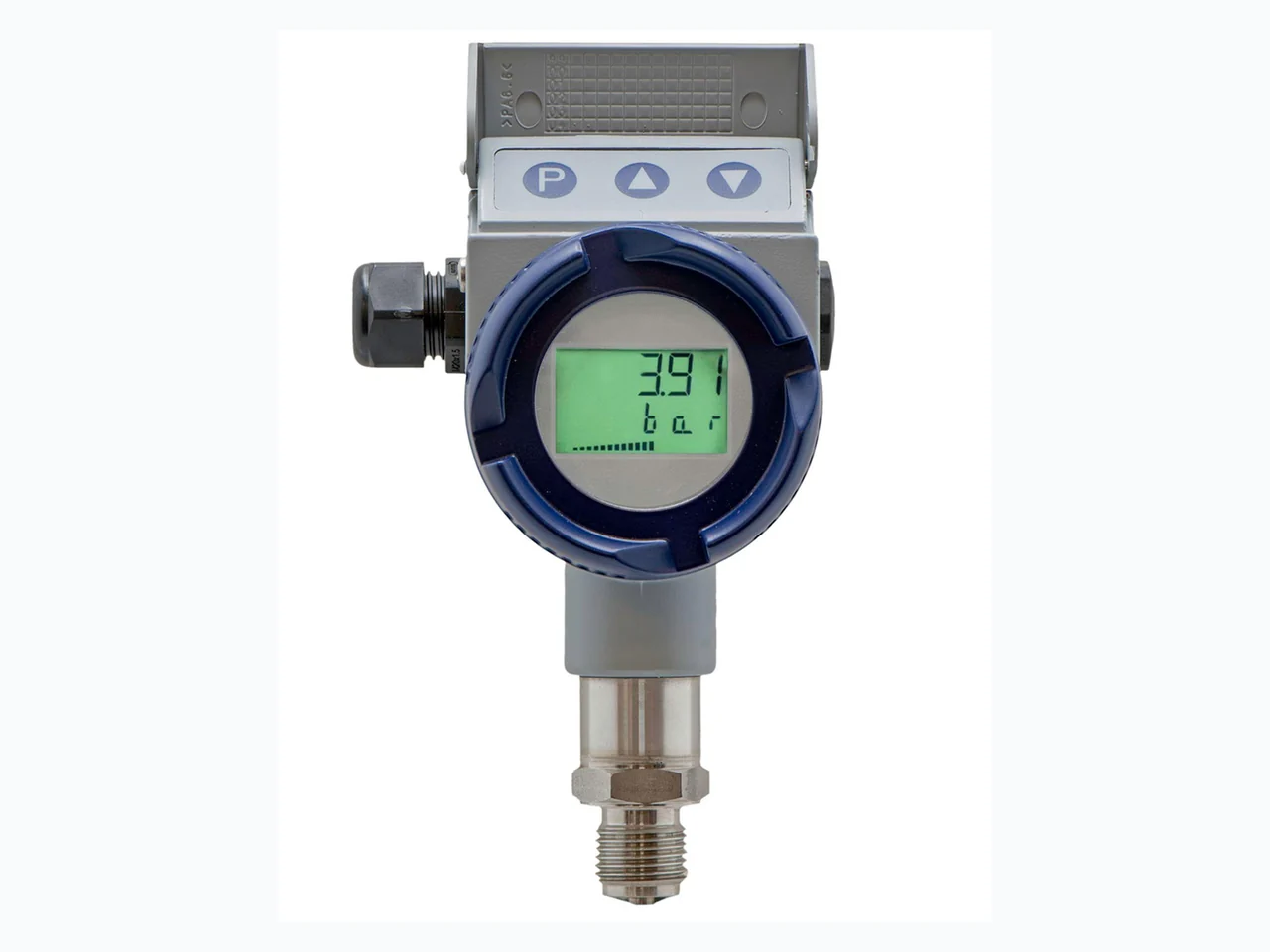
Pressure range, span, overpressure and burst pressure are not interchangeable
A sensor selected only from its nominal measuring range can still fail or produce poor data. Normal pressure, vacuum, startup transients, pump pulsation, valve closure and cleaning pressure all matter. The pressure range must also match the accuracy required at the operating point.
| Term | Meaning | Why it matters |
|---|---|---|
| LRV / URV | Lower and upper range values used to define a configured transmitter range. | LRV and URV can often be configured within the transmitter’s permitted sensor range; allowable span and turndown remain device-specific. |
| Span | URV − LRV. | Accuracy may be stated as a percentage of span, calibrated span, reading or sensor upper range; these are not equivalent. |
| Overpressure | Pressure the device can withstand without permanent loss of specified performance, according to the manufacturer’s conditions. | It is a survival/performance limit, not an extension of the calibrated range. |
| Burst pressure | Pressure associated with mechanical rupture or loss of containment. | Burst rating is a safety-related mechanical limit and must not be used as an operating pressure. |
| Static pressure (DP) | Common line pressure applied to both sides of a differential pressure cell. | A transmitter may measure a small Δp while both ports are exposed to much higher process pressure. |
Pressure sensors can provide raw, analogue, switching or digital outputs
A bare sensing element may provide a millivolt bridge signal. Industrial transmitters add excitation, compensation and signal conditioning so the receiving system gets a standard interface. The required wiring depends on the exact output and power arrangement.
Continuous measurement
- 4–20 mA is common for process transmitters and long cable runs.
- 0–10 V and other voltage outputs are common in machinery, building systems and shorter analogue runs.
- Digital communication may carry the pressure value, diagnostics and configuration data.
- Ratiometric or millivolt outputs require a compatible excitation and measurement circuit.
Pressure switch
- Changes state when pressure crosses a configured threshold.
- Electronic switches may use PNP, NPN or push-pull transistor outputs.
- Switching hysteresis prevents rapid chatter around the set point.
- A switching output does not replace a continuous pressure value unless the device provides both.
The process connection and wetted materials are part of the sensor
Pressure must reach the sensing diaphragm without leakage, blockage, chemical attack or an unwanted pressure head. Thread, flange, hygienic connection, flush diaphragm, impulse line or remote diaphragm seal should be chosen from the medium and mechanical installation rather than from electrical specifications.
| Interface | Where it fits | Main checks |
|---|---|---|
| Threaded process connection | General machinery, hydraulics, pneumatics and many process services. | Thread form, sealing method, torque, pressure rating and dead volume. |
| Flush diaphragm | Viscous, coating, hygienic or particle-bearing media where a recessed pressure port may plug. | Diaphragm material, cleaning method, allowable mechanical contact and process temperature. |
| Impulse piping / manifold | Remote pressure taps and differential-pressure measurement. | Slope, trapped gas or liquid, leak tightness, valve sequence, equalisation and freezing risk. |
| Remote diaphragm seal | Hot, corrosive, viscous, sanitary or difficult process connections. | Fill-fluid compatibility, capillary length, elevation head and ambient/process temperature effects. |
Mounting and impulse lines can shift an otherwise accurate pressure measurement
Direct-mounted sensors avoid impulse-line errors but expose the instrument to process temperature, vibration and pressure pulsation. Remote piping protects or relocates the transmitter, but adds possible leak points, trapped phases and hydrostatic head.
Pressure spikes and pulsation can matter more than the steady reading
Pumps, reciprocating compressors, fast valves and hydraulic circuits can produce pressure peaks that a slow display never shows. Repeated pulsation can also fatigue diaphragms, fittings and impulse lines. Check transient and pulsation limits separately from the steady-state measuring range.
How do you choose an industrial pressure sensor?
Define gauge, absolute or differential pressure first. Set the normal range and credible transients, then match the required accuracy, temperature performance, wetted materials, process connection, output, supply and environmental rating to the installation.
- Choose the pressure reference. Gauge, absolute and differential devices are not interchangeable when atmospheric pressure or a second process pressure matters.
- Define the full pressure envelope. Include vacuum, normal operation, startup, cleaning, blocked-line conditions, pulsation and credible pressure spikes.
- Set the measurement performance. Check accuracy at the intended span, temperature effects, stability, response time and the resolution of the receiving system.
- Match wetted materials. Verify diaphragm, process fitting, seals and fill fluid against corrosion, permeation, hydrogen service, sanitation and cleaning requirements.
- Select the mechanical connection. Thread, flange, flush diaphragm, manifold or remote seal must fit the process and maintenance method.
- Match the electrical interface. Confirm supply voltage, 4–20 mA or voltage output, switching logic, digital protocol, isolation and PLC/input compatibility.
- Check the installation environment. Consider ambient temperature, ingress protection, vibration, hazardous-area requirements and cable entry.
- Plan calibration and replacement. Provide isolation, vent/drain access and a practical way to apply a known pressure without disturbing more of the process than necessary.
Troubleshooting pressure measurement errors
Separate sensor faults from process-interface faults. A transmitter can be electrically healthy while a blocked pressure port, trapped gas, liquid head or manifold error prevents the actual process pressure from reaching the sensing cell correctly.
| Symptom | Checks |
|---|---|
| Constant zero offset | Reference type, mounting orientation, hydrostatic head, trapped pressure, atmospheric vent, zero trim and calibration setup. |
| Reading is slow | Blocked port, viscous medium, long impulse line, restriction or snubber, trapped gas/liquid, remote-seal response and transmitter damping. |
| Signal is noisy | Real pulsation, pump/compressor cycles, vibration, grounding/shielding, unstable supply, loose wiring and incorrect damping or filtering settings. |
| DP reading drifts | Unequal impulse-line head, leaks, temperature differences between legs, trapped phases, manifold leakage and static-pressure effects. |
| Gauge sensor changes with weather | If the process pressure is fixed on an absolute basis, a gauge reading will move as atmospheric pressure changes; also inspect the vent path for blockage, moisture or contamination. |
| Output is at a limit or fault value | Applied pressure versus configured range, sensor diagnostics, loop supply/burden, wiring polarity, output scaling and device-specific fault behaviour. |