
Proximity Sensors: Inductive, Capacitive, Photoelectric & Selection
A proximity sensor detects the presence or approach of an object without mechanical contact. Inductive sensors are the standard choice for nearby metal targets, while capacitive, photoelectric, ultrasonic and magnetic sensors cover non-metals, longer ranges, transparent or irregular targets, liquid and powder detection, and magnet-based position sensing.
Choose the sensing principle from the target material and required distance, then check target size, approach direction, mounting, hysteresis, switching frequency, PNP/NPN logic, NO/NC function, supply voltage and the real environment around the sensing face.
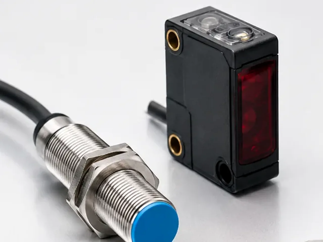
A rated sensing distance is not a guaranteed installation gap for every target. Material, target size, sensor mounting and temperature can move the switching point, so the working distance should include margin.
Which proximity sensor type fits the target?
The word proximity describes the task, not one sensing technology. A metal part a few millimetres from a machine frame calls for a different sensor than a carton on a conveyor, a liquid behind a plastic wall or a piston magnet inside a pneumatic cylinder.
| Technology | Typical target | Strength | Main limitation |
|---|---|---|---|
| Inductive | Metal | Short-range, robust machine-position and part-presence detection with no optical alignment. | Sensing distance changes with target metal, size and mounting; non-metallic targets are not detected. |
| Capacitive | Metal, plastic, glass, powders and liquids | Can detect non-conductive material and, in some applications, product through a non-metallic wall. | Moisture, deposits and nearby material can shift sensitivity and create false switching. |
| Photoelectric | Most opaque or reflective objects | Much longer range than most inductive or capacitive sensors and flexible detection geometry. | Target colour, gloss, transparency, contamination and alignment can affect performance depending on optical mode. |
| Ultrasonic | Solid or liquid surface | Distance and presence detection largely independent of target colour or visible contrast. | Dead zone, target angle, air turbulence, foam and temperature can influence the echo. |
| Magnetic | Permanent magnet or magnetised actuator | Can detect a magnet through many non-ferrous housings; common on pneumatic cylinders. | Requires a suitable magnetic target and correct field orientation. |
How does an inductive proximity sensor detect metal?
An inductive sensor drives a coil at its active face to create an alternating electromagnetic field. When a conductive target enters that field, eddy currents are induced in the metal. The resulting losses change the oscillator condition, and the electronics convert that change into a discrete switching output.

Inductive detection is attractive on machinery because dust, oil mist and target colour normally matter less than they do for optical sensing. It is still not immune to installation effects: surrounding metal, target alloy, target thickness, target size, sensor-to-sensor spacing and temperature can all shift the switching point.
Rated sensing distance, operating distance and hysteresis are different
For an inductive sensor, the rated operating distance is a reference measured with a standard target. The installation gap should stay within the assured operating range for the model; target material and size, mounting, supply voltage and temperature can shift the switch point. Hysteresis is the difference between the operate and release distances.
Sensing distance
- Read the datasheet definition, not only the headline millimetre value.
- Check the standard target material and dimensions used for the rating.
- Apply manufacturer reduction factors or curves for stainless steel, aluminium, brass, copper or unusually small targets.
- Leave mechanical tolerance so the target cannot strike the active face.
Hysteresis
- The target normally switches at one distance while approaching and another while moving away.
- That difference prevents chatter when the target vibrates near the switching boundary.
- Too little installation margin can still create repeated ON/OFF transitions despite normal sensor hysteresis.
- Repeatability and hysteresis are separate specifications.
Flush mounting, non-flush mounting and target geometry change the result
Many cylindrical inductive sensors are offered as flush-mountable (shielded) or non-flush (unshielded) versions. A flush sensor can be embedded in surrounding metal as specified by the manufacturer. A non-flush sensor needs free space around the active face because part of its sensing field extends sideways.
Capacitive, photoelectric, ultrasonic and magnetic sensors solve different proximity tasks
Maximum range alone is a poor selection criterion. The sensing principle must distinguish the target from its background throughout the expected contamination, vibration, misalignment and product variation.
PNP, NPN, NO/NC and wire count describe the interface, not the sensing principle
An inductive sensor and a photoelectric sensor can use the same electrical output even though they detect objects in completely different ways. Match the sensor output to the PLC or controller input and to the required fail behaviour.
DC transistor outputs
- PNP and NPN describe how a transistor output switches current relative to the supply rails.
- NO and NC describe the logical output state relative to whether the target is detected.
- Three-wire DC sensors commonly use separate positive supply, 0 V and output conductors.
- Four-wire models may provide complementary NO/NC outputs, teach/configuration conductors or additional functions.
Two-wire sensors
- The sensor electronics and load share the same two conductors.
- Off-state leakage current and on-state voltage drop can matter to PLC input compatibility.
- AC, DC and universal two-wire models are not interchangeable.
- Use the exact wiring diagram and permitted load range for the model.
Contamination, temperature, vibration and nearby objects can move the switching margin
Bench testing can miss installation effects. Contamination, nearby material, temperature and bracket movement can change the sensing field or target contrast, so the sensing face and mounting bracket must be evaluated as part of the installation.
| Condition | Likely effect | Design response |
|---|---|---|
| Metal chips around inductive sensor | Build-up can act as a target or reduce the available field margin. | Use chip-resistant construction where needed and keep the active area clear. |
| Water, coating or dust on capacitive sensor | Changes dielectric conditions and can shift the sensitivity threshold. | Set only the sensitivity needed for reliable target detection, then verify the teach/threshold setting with the expected deposits or moisture present. |
| Dirty photoelectric lens | Reduces transmitted or received light and may narrow operating reserve. | Provide access for cleaning and use sufficient excess gain rather than marginal alignment. |
| Hot or cold machine | Sensing distance and electronics characteristics can drift within specified limits. | Check the operating-temperature range and recommended working distance across the full cycle. |
| Bracket vibration | Mechanical movement can repeatedly cross the switching boundary. | Stiffen the bracket and increase electrical/mechanical distance margin. |
| Adjacent sensors | Mutual interference can destabilise switching for inductive, capacitive or ultrasonic devices. | Follow minimum spacing or synchronisation/frequency instructions for the exact model. |
How do you choose an industrial proximity sensor?
Start with the exact target material, minimum target size and required detection distance. Then check mounting space, approach direction, switching speed, hysteresis and repeatability, PNP/NPN and NO/NC output, supply voltage, connector or cable, temperature, ingress protection and contamination before fixing the final operating gap.
- Define the target. Record material, dimensions, surface, colour or transparency, and whether a magnet is available.
- Choose the sensing principle. For short-range metal detection, inductive is usually the first choice; use capacitive, photoelectric, ultrasonic or magnetic sensing when the target or required distance calls for another principle.
- Set a realistic distance. Use the datasheet’s rated, usable and assured operating-distance definitions correctly, and leave enough mechanical tolerance to prevent contact with the sensing face.
- Check mounting. Confirm flush/non-flush rules, free-zone dimensions, bracket stiffness and sensor-to-sensor spacing.
- Match the dynamics. Switching frequency and response time must suit the fastest target speed and smallest gap between targets.
- Match the electrical interface. Confirm DC or AC supply, PNP/NPN, NO/NC, two-/three-/four-wire arrangement, load current and PLC input compatibility.
- Check the environment. Consider temperature, washdown, oils, coolants, weld fields, metal chips, dust, vibration and hazardous-area requirements where applicable.
- Commission under worst-case conditions. Test minimum and maximum target tolerance, expected contamination and the full operating-temperature cycle before locking the bracket position.
Troubleshooting unstable or missing proximity sensor signals
First decide whether the sensor is failing to detect the target or whether the electrical output is failing to reach the controller. The status LED is useful, but it does not prove that the PLC input sees the correct voltage or current.
| Symptom | Checks |
|---|---|
| Sensor never switches | Target material and size, actual gap, supply voltage, wiring, output type, active-face orientation and whether the target enters the specified sensing zone. |
| Sensor stays switched | Nearby metal or product, contamination on sensing face, non-flush sensor mounted too deeply, capacitive sensitivity set too high, wiring short or failed output stage. |
| Switch point changes | Temperature, bracket movement, target alloy or geometry, deposits, supply variation and sensor replacement with a different range or mounting class. |
| Chatter near target | Insufficient distance margin, machine vibration, target wobble, excessive speed, poor optical alignment or a target crossing only the edge of the sensing field. |
| LED changes but PLC does not | PNP/NPN compatibility, common 0 V/reference, input threshold, load current, two-wire leakage/drop, cable damage and terminal assignment. |
| False detections between products | Background reflections, adjacent sensors, loose metal chips, moisture, transparent targets, ultrasonic echoes and teach/sensitivity settings. |