
Position & Distance Sensors: Linear, Rotary, Laser & Selection
Position and distance sensors measure where a machine element is, how far it has moved, or the gap to a target. Linear and rotary encoders, LVDTs, magnetostrictive sensors, laser displacement sensors, ultrasonic sensors and draw-wire devices cover different ranges, accuracies, speeds and environments.
Choose the measuring principle from the motion and target first, then check range, accuracy, repeatability, resolution, response time, mounting geometry, output interface, environmental limits and whether the controller needs an absolute value or incremental motion information.
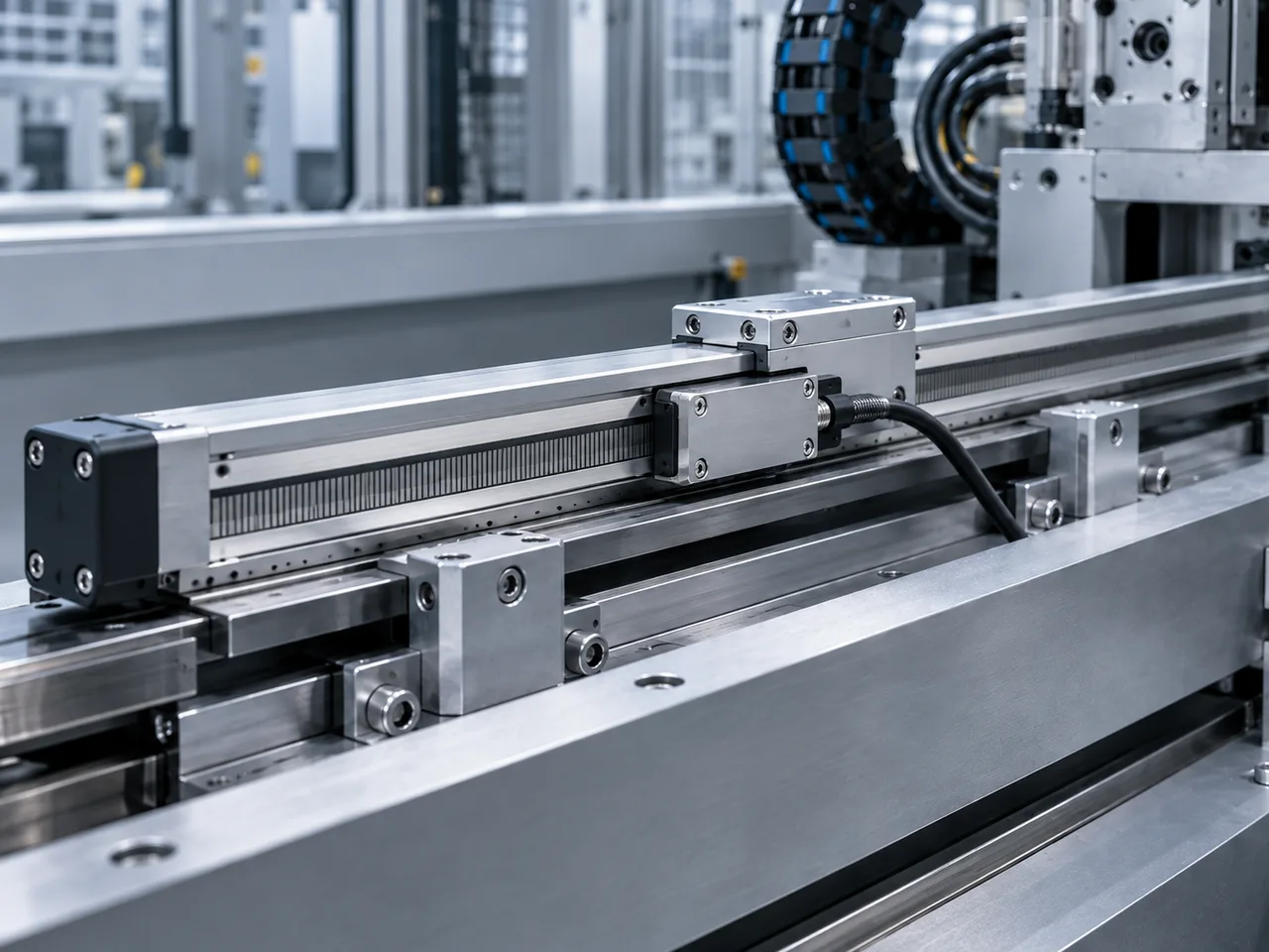
Resolution is not the same as accuracy. A sensor may report very small increments while still having larger errors from linearity, calibration, temperature, target surface, mounting or mechanical play.
Position, displacement and distance are related but not identical measurements
Start by defining what the controller actually needs. Position is a location within a defined coordinate or stroke. Displacement is a change in position. Distance is the separation between the sensor and a target or between two reference points. The same sensor family may support more than one of these tasks, but the installation and error sources can be very different.
| Task | Typical sensor | Useful when | Key concern |
|---|---|---|---|
| Linear position | Magnetostrictive, LVDT, linear encoder, potentiometric | A slide, cylinder, valve, press ram or machine axis must be located along a stroke. | Mechanical alignment, stroke length, absolute vs incremental output and installation space. |
| Rotary position | Absolute or incremental rotary encoder, resolver, rotary potentiometer | Shaft angle, turn count, speed or direction must be measured. | Resolution, maximum speed, shaft loading, coupling error and whether the system must retain or re-establish position after power-up. |
| Short-range displacement | Laser triangulation, eddy-current, capacitive or contact probe | Small changes in height, thickness, run-out, gap or vibration must be resolved. | Surface condition, target material, alignment, temperature drift and required bandwidth. |
| Stand-off distance | Laser time-of-flight, ultrasonic, photoelectric distance sensor | The target is separated from the sensor by centimetres or metres. | Target reflectivity or acoustic response, blind zone, beam geometry and environmental effects. |
Linear position sensors differ mainly in contact method, reference behaviour and stroke
Linear position feedback may be mechanically linked to the moving part or measured without sliding electrical contact. Potentiometric sensors are simple and directly proportional over their electrical stroke, but the wiper is a wear element. LVDTs use a moving magnetic core inside a transformer structure and can provide frictionless measurement when the core is mechanically coupled without rubbing the coil assembly.
For hydraulic or pneumatic cylinders, a magnetostrictive rod sensor can be integrated into the cylinder so the position magnet follows the piston without mechanical contact with the sensing element. For short precision strokes, LVDTs and linear encoders are common alternatives. Choose among them from the required stroke, uncertainty, motion speed and installation geometry.
Incremental encoders measure relative motion; absolute encoders report shaft position
An incremental encoder produces pulses as the shaft moves. A controller counts those transitions to determine relative displacement and can use two phase-shifted channels to determine direction. An index channel may provide one reference event per revolution. An absolute encoder instead reports a code representing shaft position, so the controller can recover position without counting every pulse from a previously established origin.
Incremental encoder
- Best when speed, direction and relative movement are needed.
- Position normally depends on a reference or homing procedure after power-up unless the control system preserves position by another method.
- Pulse frequency rises with both shaft speed and resolution.
- Line-driver signalling is often preferred for higher frequency or longer cable runs.
Absolute encoder
- Reports a unique position code rather than requiring accumulated pulse counts.
- Single-turn versions resolve one revolution; multi-turn versions also track revolutions. Check how multi-turn position is retained through power loss because the method depends on the encoder design.
- Interfaces may include parallel, SSI, serial or industrial network protocols depending on the model.
- Mechanical coupling and shaft loading still affect the installed measurement.
Resolvers are electromagnetic rotary position transducers used where a rugged shaft-angle measurement is required, especially in motor and servo applications. They produce angle-dependent sine and cosine signals and require excitation plus resolver-to-digital or equivalent signal conditioning in the controller.
Laser triangulation and time-of-flight cover different distance ranges
Reflective laser displacement sensors commonly use triangulation for short, precise measurements. The sensor projects a spot on the target; a receiving lens images the reflected light onto a position-sensitive detector. As the target moves, the return angle changes and the image moves across the receiver. This geometry is well suited to displacement, height, thickness and run-out measurements where a small change in target position must be resolved quickly.
Triangulation
- Commonly used for short-range displacement and dimensional measurement.
- Spot size, target slope, surface texture, gloss and colour can change the received optical distribution.
- Mounting angle matters because the receiver must see the reflected spot throughout the measuring range.
- High sampling rates are available for vibration, run-out and fast production measurements.
Optical time-of-flight
- Measures the return time or phase of emitted light and is generally used for longer stand-off distances.
- Distance follows the round-trip travel relation rather than the triangulation angle.
- Beam divergence, target reflectivity, ambient light and minimum signal level still matter.
- Confirm the specified range separately for dark, reflective or small targets.
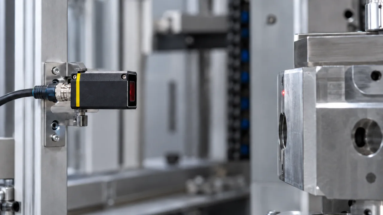
Ultrasonic sensors handle optically difficult targets; draw-wire sensors cover long strokes
An ultrasonic distance sensor emits a sound burst and measures the time until the echo returns. Because the measurement is acoustic, colour and visible transparency are far less important than for optical sensing. The target must still return a usable echo: steep angles can reflect sound away from the sensor, and soft, porous or highly irregular surfaces can reduce or scatter the signal.
A draw-wire sensor, also called a cable-extension or string sensor, converts linear movement into rotation. A spring-loaded spool keeps a measuring cable under tension while an internal potentiometer or encoder measures spool rotation. This makes long linear strokes possible from a compact housing and can simplify installation where a rigid rod or long scale is impractical.
| Technology | Good fit | Watch for |
|---|---|---|
| Ultrasonic | Object distance, level surface, large or transparent targets, applications where visible colour varies. | Blocking distance, temperature, air movement, target angle, foam, multiple echoes and sensor-to-sensor interference. |
| Draw-wire | Long stroke, telescoping structures, lifts, mobile machinery and applications with little room for a full-length rigid transducer. | Cable alignment, side loading, cable abrasion, spool dynamics, spring tension and contamination around the cable outlet. |
Output type must match the cable run and controller interface
Continuous position sensors commonly provide analogue or digital measurement values. A simple threshold output such as PNP/NPN only indicates whether a programmed position or distance condition has been crossed; it does not by itself provide the full measured position.
| Interface | Typical use | Design point |
|---|---|---|
| 0–10 V | Simple analogue position or distance feedback over short to moderate cable runs. | Voltage drop is usually small because input current is low, but common reference, noise and ground differences can affect the measurement. |
| 4–20 mA | Industrial analogue feedback where cable length, electrical noise or fault discrimination favour a current loop. | Check loop supply and load resistance so the transmitter retains enough compliance voltage across the full current range. |
| Incremental A/B/Z | Encoder position, speed and direction. | Match electrical output type, receiver threshold, cable, shielding and maximum input frequency. |
| Absolute serial / SSI | Direct digital position value without pulse accumulation. | Match word length, clock rate, coding, electrical layer and controller support. |
| IO-Link / fieldbus | Measurement value plus diagnostics, configuration or multiple process values. | Update time, network cycle, data format and deterministic behaviour must suit the control task. |
Resolution, repeatability, linearity and bandwidth describe different limits
A position sensor can have fine resolution without high absolute accuracy. Accuracy is the closeness of the indicated value to the true position, repeatability is the spread when the same position is measured repeatedly, linearity describes deviation from the ideal transfer curve, and resolution is the smallest reportable change.
| Specification | What it tells you | Common mistake |
|---|---|---|
| Measuring range / stroke | The physical interval over which the device is specified to measure. | Using the full range with no allowance for mechanical end stops, target tolerance or blind zones. |
| Accuracy | How close the reported value can be to the reference value under stated conditions. | Replacing the accuracy requirement with the display resolution or encoder count size. |
| Repeatability | How closely repeated readings agree at the same target position. | Assuming good repeatability removes systematic calibration or linearity error. |
| Resolution | The smallest change the sensor or digital interface can distinguish or report. | Treating one encoder count or one ADC bit as guaranteed measurement accuracy under operating conditions. |
| Linearity | Deviation of the transfer characteristic from the specified straight-line relationship. | Ignoring whether the datasheet value is % of full scale, % of reading or an absolute unit. |
| Sampling / response | How quickly the sensor updates and responds to moving targets. | Selecting only from static accuracy while the actual target is moving or vibrating. |
| Temperature coefficient | How the output or zero/span can shift with temperature. | Calibrating at room temperature and assuming the same uncertainty on a hot machine. |
How do you choose a position or distance sensor?
Define the motion first: linear or rotary, absolute or relative, contact or non-contact, measuring range and maximum speed. Then set the required accuracy and repeatability, choose a sensing principle that works with the target and environment, and finally match the output, mounting, cable and controller interface.
- Define the measurand. State whether you need absolute position, displacement from a reference, shaft angle, speed, gap, height or stand-off distance.
- Set the range and mechanical limits. Include overtravel, end-stop tolerance, blind zones, cable travel and mounting clearances rather than using only the nominal working stroke.
- Set the measurement requirement. Separate accuracy, repeatability, resolution and update rate. Use the worst-case machine tolerance rather than a display-digit target.
- Choose the physical principle. Use LVDT, magnetostrictive, encoder, potentiometric, laser, ultrasonic, draw-wire or another technology according to motion, target, stroke and environment.
- Check mounting geometry. Consider alignment, shaft coupling, bearing load, scale straightness, laser angle, acoustic cone, cable pull direction and vibration.
- Check dynamics. Maximum shaft speed, acceleration, target speed, sampling rate, response time and controller input frequency must work together.
- Match the electrical interface. Confirm analogue range, encoder electrical output, serial protocol, supply, grounding, shielding and PLC/DAQ input compatibility.
- Verify the environment. Temperature, washdown, oil, dust, vibration, shock, welding fields, ambient light and target contamination can dominate the final error.
- Commission against a reference. Check zero, span, end positions and repeatability on the actual machine before accepting the measurement for control or quality decisions.
Troubleshooting unstable or incorrect position and distance readings
Separate mechanical, sensing and electrical faults. A stable sensor reading can still be wrong because of coupling slip or mounting geometry, while a mechanically correct installation can produce unstable data through noise, reflections, poor target return or an overloaded interface.
| Symptom | Checks |
|---|---|
| Reading offset is constant | Zero/reference setting, mounting datum, sensor-to-target geometry, calibration offset, encoder index/reference position and mechanical coupling. |
| Error increases along the stroke | Span scaling, linearity, scale pitch, analogue input scaling, mechanical lever ratio, draw-wire spool mapping and incorrect full-scale parameters. |
| Reading jumps during motion | Loose coupling, cable damage, encoder input frequency, electrical noise, poor shield termination, optical reflections, ultrasonic false echoes and mechanical vibration. |
| Correct at low speed, wrong at high speed | Sensor response time, sampling rate, encoder maximum response frequency, controller scan/update time and motion-induced vibration. |
| Laser reading depends on the part | Surface colour, gloss, angle, transparency, spot size, receiver exposure and whether the chosen optical principle suits the target. |
| Ultrasonic reading changes with conditions | Temperature compensation, air turbulence, target angle, foam, blocking distance, condensation and competing echoes. |
| Position drifts as machine warms | Sensor temperature coefficient, machine thermal expansion, mounting structure, electronics warm-up and reference-location movement. |