
Flow & Level Sensors: Principles, Types & Selection
Flow sensors measure how quickly a liquid or gas moves through a pipe, duct or channel, while level sensors measure the height, interface or presence of material in a vessel. Selection depends on the medium, required uncertainty, process pressure and temperature, installation geometry, measuring range and output interface.
Define the measurement as volumetric flow, mass flow, continuous level or point-level detection. The next constraints are conductivity, density, viscosity, sound velocity, dielectric properties, pipe condition and target surface, according to the sensing principle.
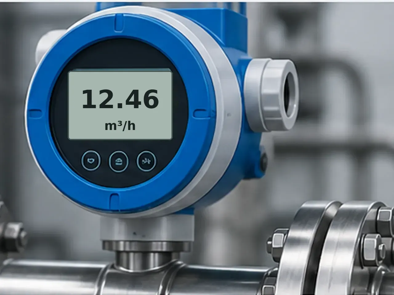
Flow rate and level are not interchangeable quantities. A tank can have a stable level while inlet and outlet flows are both high, and a flow meter can read correctly while the downstream vessel level is changing.
Define flow, quantity and level before choosing the sensor
Flow measurement can describe volumetric flow, such as litres per minute or cubic metres per hour, or mass flow, such as kilograms per hour. Volumetric flow depends on the volume moving through a section; mass flow also accounts for density. Level measurement describes the position of a material surface or interface in a vessel, or simply whether material has reached a defined high or low point.
| Task | Typical technologies | Main process dependency | Common use |
|---|---|---|---|
| Volumetric flow | Electromagnetic, ultrasonic, vortex, turbine, differential pressure | Pipe geometry, velocity profile and technology-specific fluid properties | Water, cooling circuits, process liquids, gases and utilities |
| Mass flow | Coriolis, thermal mass; volumetric meter combined with an independent density value where appropriate | Density or gas composition depending on principle | Dosing, batching, gases, chemical and energy balances |
| Continuous level | Radar, guided wave radar, ultrasonic, hydrostatic, capacitance, float | Vessel geometry, density, dielectric properties, vapour space or target surface | Storage tanks, process vessels, silos and open channels |
| Point level | Vibronic fork, capacitance, conductive probe, optical, float switch | Material contact, coating, conductivity, density or optical contrast | High-level alarm, low-level alarm, pump protection and overfill prevention |
Flow technologies measure different physical effects
Each flow principle imposes different process and installation constraints. Important differences include conductivity requirements, pressure loss, direct versus inferred mass flow, sensitivity to the velocity profile and whether the sensor can be mounted outside the pipe.
A conductive liquid moving through a magnetic field induces a voltage proportional to flow velocity. There are no internal moving parts, but the medium must meet the meter's minimum conductivity requirement and the pipe must remain full.
Vibrating tubes are driven at resonance and mass flow is derived from the phase or motion change caused by the Coriolis effect. Many meters also provide density and temperature. Pressure drop, tube size, vibration and two-phase flow still require attention.
An orifice, Venturi, nozzle or other primary element creates a differential pressure related to velocity. For common incompressible arrangements, flow varies approximately with the square root of differential pressure, so density and primary-element data matter.
A bluff body sheds alternating vortices whose frequency rises with flow velocity over the valid operating range. Vortex meters are used for liquids, gases and steam, but low Reynolds number, vibration and pulsating flow can limit performance.
Transit-time meters compare acoustic travel with and against the flow. Clamp-on versions can avoid cutting the pipe. Bubbles, solids, liner condition, acoustic coupling and the available straight pipe can influence measurement.
Heat transfer from a heated element is related to gas mass flow. The instrument is calibrated to report mass flow for specified gas properties and operating limits; gas composition, pressure, temperature and installation can still affect accuracy outside the stated compensation or calibration range.
Fluid motion turns a rotor and pulse frequency represents flow. These meters can be accurate in clean fluids but bearings, viscosity, contamination and upstream flow conditioning affect service life and calibration.
Known volumes are repeatedly trapped and transferred through the meter. This is useful for viscous liquids and totalisation, but mechanical parts create pressure loss and require clean, compatible media.
Continuous level and point-level detection solve different control problems
Continuous transmitters provide a changing value across a measuring span. Point-level devices switch when the material reaches a defined position. A vessel may use both: a continuous radar transmitter for normal control and an independent high-level switch for protection.
Non-contact and wave-based
- Radar measures microwave travel to the material surface and is widely used for liquids and bulk solids. Antenna position, false echoes, internal structures and dielectric behaviour must be considered.
- Guided wave radar sends a pulse along a probe. It can measure level and, in suitable applications, interfaces, but the probe contacts the process and must tolerate coating, forces and vessel geometry.
- Ultrasonic measures acoustic echo time. Temperature compensation is important because sound velocity changes with air temperature; steam, vapour, foam and turbulence can weaken or distort echoes.
Contact and pressure-based
- Hydrostatic pressure infers liquid height from pressure at a known datum. It is simple and robust, but density changes directly alter the indicated level unless compensated.
- Capacitance detects the change in electrical capacitance between a probe and the vessel or reference electrode. Product dielectric constant, buildup and conductive coating can affect calibration.
- Float, vibronic and conductive switches are common for point-level alarms. Selection depends on density, viscosity, coating, conductivity and whether moving parts are acceptable.
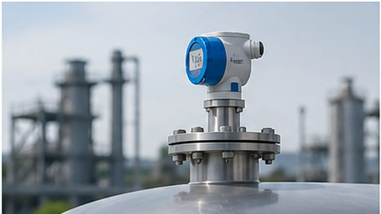
Pipe condition and installation geometry can dominate flow-meter error
A flow meter is calibrated as an instrument, but the installed result also depends on the pipe and the velocity profile reaching the sensor. Elbows, partially open valves, pumps, reducers and tees can create swirl or asymmetric flow. Required upstream and downstream straight lengths vary by technology, meter design and disturbance, so use the manufacturer's installation limits rather than a single generic diameter rule.
Level accuracy starts with the vessel datum and measurement path
Level instruments need a known reference point. The configured empty and full positions must correspond to the actual vessel geometry, not simply to the nozzle height. Internal ladders, agitators, heating coils, filling streams and sloped vessel bottoms can create false echoes or make the relationship between level and volume non-linear.
| Technology | Installation concern | Process effect |
|---|---|---|
| Radar | Nozzle geometry, antenna clearance, vessel internals and false-echo mapping | Low dielectric return, foam, heavy condensation or difficult surfaces can reduce signal margin depending on frequency and antenna design. |
| Guided wave radar | Probe length, anchoring, clearance from walls and internals | Buildup, interface conditions and mechanical forces on long probes can affect performance. |
| Ultrasonic | Clear acoustic cone, blocking distance and target angle | Temperature, steam, vapour, turbulence and foam can change echo quality or sound propagation. |
| Hydrostatic / DP | Pressure datum, impulse line or remote seal arrangement | Density, vapour-space pressure and temperature-induced fill-fluid effects can shift the calculated level. |
| Capacitance / probe | Probe clearance, vessel reference and insulation | Dielectric constant, coating and conductive buildup can change the measured capacitance. |
Match the measurement output to the control and diagnostic requirement
Flow and level devices can provide a continuous analogue value, pulses for totalisation, switching outputs or a digital process value. The sensing principle does not determine the electrical interface: the same radar or flow technology may be available with several output options.
| Output | Typical use | Design point |
|---|---|---|
| 4–20 mA | Continuous flow or level transmitter value, often with HART on process instruments | Check loop voltage, load, fault signalling, isolation and the configured lower/upper range values. |
| 0–10 V | Compact sensors and shorter industrial analogue runs | Reference potential, cable noise and input impedance matter more than with a current loop. |
| Pulse / frequency | Flow totalisation, turbine, vortex or batch counting | Confirm pulse weighting, maximum frequency, output electrical type and counter behaviour during power loss. |
| Switching output | High/low level, flow present, flow threshold or dry-run protection | Check PNP/NPN or relay logic, fail-safe state, hysteresis and whether the output is independent from the main transmitter. |
| IO-Link / fieldbus | Process value plus diagnostics, totalisers, temperature, density or configuration | Cycle time, device profile, data mapping, network availability and controller support must suit the control function. |
Accuracy specifications must be read with range, fluid and operating conditions
Interpret accuracy from the stated error basis and operating conditions. Check whether error is specified as a percentage of reading, percentage of full scale or an absolute value, and whether zero stability, repeatability, temperature effects and low-end limits are stated separately. A wide nominal range does not imply equal uncertainty at every point in that range.
| Specification | What to check | Typical mistake |
|---|---|---|
| Accuracy / uncertainty | Basis of error, reference conditions and whether transmitter, sensor and primary element are included | Comparing % of reading with % of full scale as if they were equivalent. |
| Repeatability | Scatter at the same process condition | Assuming repeatability removes zero, calibration or installation bias. |
| Turndown / low-flow limit | Usable range above the minimum stable or specified flow | Selecting from maximum capacity and ignoring uncertainty near zero. |
| Response / damping | Sensor update, filtering and process dynamics | Using heavy damping to hide noise and then missing real fast process changes. |
| Density / composition | Whether the principle or compensation assumes constant density or gas composition | Applying one calibration to fluids whose properties change materially. |
| Dead zone / blocking distance | Minimum measurable distance for ultrasonic or radar level devices | Placing the maximum material level inside the sensor's near-field exclusion zone. |
How do you choose a flow or level sensor?
Specify the measurand and medium before comparing instrument families. Define volumetric or mass flow, continuous or point level, the minimum/normal/maximum range, required uncertainty and response. Exclude technologies that conflict with conductivity, density, viscosity, solids, bubbles, foam, vapour, pressure, temperature, hazardous-area requirements or available installation geometry.
- Define the measurement. State the actual control variable and units: mass flow, volumetric flow, totalised quantity, continuous level, interface or high/low point level.
- Describe the medium. Record liquid or gas, conductivity, density range, viscosity, solids, bubbles, corrosiveness, dielectric behaviour and whether composition changes during operation.
- Set the operating envelope. Include minimum, normal and maximum flow or level, pressure, temperature, cleaning conditions, vacuum and upset conditions rather than only the nominal duty point.
- Set the measurement requirement. Separate accuracy, repeatability, turndown, response time and totalisation needs. Specify where in the operating range the requirement must be met.
- Check installation constraints. Pipe diameter, straight run, full-pipe condition, available tank nozzle, vessel internals, sensor insertion depth and service access can eliminate otherwise suitable technologies.
- Check process disturbance. Pumps, valves, pulsation, two-phase flow, foam, vapour, agitation, filling streams and buildup can change the signal seen by the sensor.
- Match materials and approvals. Verify wetted materials, pressure rating, temperature, hygienic or sanitary design, hazardous-area approval and required ingress protection.
- Match the interface. Select analogue, pulse, switch or digital output to suit the PLC/DAQ, cable run, totaliser and diagnostic requirement.
- Define commissioning checks. Provide a method to confirm zero, span, totalisation or level datum during commissioning and maintenance.
Troubleshooting unstable or incorrect flow and level readings
Check the process condition before adjusting calibration. Many apparent sensor faults are caused by an empty pipe, entrained air, changing density, poor acoustic coupling, false echoes, blocked impulse lines or a moving vessel reference rather than by the electronics.
| Symptom | Checks |
|---|---|
| Flow reads low or high by a stable percentage | Pipe diameter and scaling, meter factor, density compensation, analogue range, primary-element data, zero setting and whether the installed pipe is actually full. |
| Flow signal is noisy | Bubbles, cavitation, pump pulsation, valve position, vibration, grounding, shielding, velocity profile and whether damping is masking a process problem. |
| Magnetic flow meter falls to zero intermittently | Empty-pipe condition, electrode coating, low conductivity, grounding/potential equalisation, cable integrity and transmitter diagnostics. |
| Radar level jumps between values | False echoes from nozzles or internals, filling stream, agitator position, surface turbulence, antenna buildup, condensation and configured echo suppression. |
| Hydrostatic level changes when product changes | Actual liquid density, vapour-space pressure, temperature, remote seal fill fluid and the pressure reference arrangement. |
| Ultrasonic level is worse during hot or steamy operation | Temperature compensation, vapour gradients, steam, condensation, foam, blocking distance and available echo strength. |
| Point-level switch stays actuated | Product buildup, mechanical float freedom, fork coating, conductive bridges, output fail-safe logic and actual material level. |