
Vibration & Acceleration Sensors: Types, Mounting & Selection
Vibration and acceleration sensors measure dynamic mechanical motion on machines and structures. Piezoelectric accelerometers are widely used for broad-band industrial vibration, MEMS accelerometers extend measurement toward static and low-frequency acceleration, and eddy-current proximity probes measure relative shaft displacement on rotating machinery.
Choose the measurement quantity and frequency band before the sensor package. Acceleration, velocity and displacement emphasise different parts of a vibration spectrum, while mounting stiffness, sensor resonance, cable behaviour, temperature and signal conditioning can materially change the installed result.

An accelerometer does not directly measure “machine condition”. It measures acceleration versus time. Velocity, displacement, spectra, envelopes and alarm values are derived from that signal or measured with other transducers.
Acceleration, velocity and displacement describe the same motion differently
Mechanical vibration is oscillatory motion about an equilibrium position. The same single-frequency motion can be described as displacement, velocity or acceleration, but each quantity weights frequency differently. This matters when comparing sensors, alarm limits and historical data: two instruments can observe the same machine while reporting very different numerical values because they measure or process different quantities.
| Quantity | Typical units | Useful emphasis | Common measurement route |
|---|---|---|---|
| Acceleration | m/s² or g | Higher-frequency vibration, impacts, bearing and gear detail | Piezoelectric or MEMS accelerometer |
| Velocity | mm/s, often RMS | Overall machine vibration across a defined mid-frequency band | Electrodynamic velocity transducer or integrated accelerometer signal |
| Displacement | µm or mil, often peak-to-peak | Low-frequency motion and relative shaft movement | Eddy-current proximity probe or double-integrated acceleration where appropriate |
| Static / quasi-static acceleration | m/s² or g | Tilt, slow motion and gravity-referenced acceleration | DC-capable MEMS accelerometer |
Piezoelectric sensors are the standard choice for broad-band machine vibration
A piezoelectric accelerometer contains a seismic mass coupled to a piezoelectric element. When the sensor base accelerates, inertial force acts on the element and produces electrical charge related to acceleration. These sensors are robust, have wide usable frequency ranges and tolerate large dynamic signals, but they cannot measure true DC acceleration because the piezoelectric charge gradually leaks through the electrical system.
IEPE accelerometer
- Contains built-in impedance-conversion electronics and is powered by a constant-current source from the measurement system.
- Provides a low-impedance voltage signal that is convenient for longer industrial cable runs.
- Check sensitivity, bias voltage, excitation current, compliance voltage and the measurement input's IEPE support.
- Upper temperature is limited by the internal electronics as well as the sensing element.
Charge-mode accelerometer
- Outputs charge from the piezoelectric element and requires a charge amplifier or suitable charge input.
- Useful where the sensor itself must tolerate temperatures beyond typical integrated-electronics limits.
- Cable capacitance, insulation, connector cleanliness and triboelectric cable noise need closer control.
- The sensor, cable and amplifier must be treated as one measurement chain.
MEMS accelerometers add DC response; velocity transducers remain useful in specific bands
MEMS accelerometers use a micro-machined proof mass and electronic transduction, commonly capacitive. Unlike piezoelectric accelerometers, many MEMS devices measure down to DC, so one sensor can capture gravity, tilt, slow motion and vibration within its specified bandwidth. Industrial vibration models are selected for low noise, adequate bandwidth, shock survival and stable sensitivity rather than simply for the highest digital sample rate.
MEMS and piezoelectric technologies overlap substantially in modern condition monitoring. Compare them by the lowest frequency of interest, highest useful frequency, noise floor, full-scale acceleration, power budget, temperature and whether the node must perform local digital processing or wireless transmission.
Eddy-current proximity probes measure relative shaft motion without contact
An eddy-current proximity probe produces a high-frequency electromagnetic field at its tip. A conductive target, typically a steel shaft, changes the probe impedance as the gap changes. The probe system converts that change to a voltage representing distance. In rotating machinery with fluid-film bearings, this provides direct information about shaft motion relative to the bearing or probe mounting structure rather than casing acceleration.
| Item | Why it matters | Check |
|---|---|---|
| Initial gap | Places the operating point inside the calibrated linear range | Set the mechanical/electrical gap to the probe-system specification before judging dynamic vibration. |
| Target material | Eddy-current response depends on electrical and magnetic properties | Use the target material for which the system is calibrated or apply the manufacturer's stated correction/calibration. |
| Probe system matching | Probe, extension cable and driver form a calibrated electrical system | Do not mix cable lengths or system families unless the manufacturer explicitly permits it. |
| Mechanical reference | The probe measures shaft motion relative to its mount | Mount rigidly to the bearing structure and avoid brackets whose own vibration becomes part of the reading. |
Mounting stiffness and location control the usable high-frequency response
For casing vibration, the accelerometer should be coupled to a rigid part of the machine close to the bearing or load path of interest. A clean, flat mounting surface and a stud connection generally provide the stiffest mechanical path and the highest usable frequency. Adhesive pads and magnetic bases are useful for temporary work, but the added interface compliance lowers the mounted resonance and can alter high-frequency amplitude.
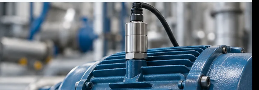
Measure where vibration can reach the sensor through a stiff structural path. Thin covers, guards, cooling fins and unsupported brackets can resonate independently of the bearing housing.
Align the sensitive axis with the radial, axial or structural direction required by the measurement plan. Triaxial sensors simplify orientation but do not remove mounting errors.
Keep the contact face clean and flat. Burrs, paint layers, excessive adhesive or uneven magnetic contact can introduce compliance and reduce repeatability.
Secure the cable near the sensor without creating a tight bend. Connector motion, rubbing, electromagnetic pickup and triboelectric effects can contaminate low-level signals.
The sensor output determines the required excitation, amplifier and acquisition input
Raw vibration sensors are not interchangeable with standard process transmitters. An IEPE accelerometer requires constant-current excitation and produces an AC voltage riding on a DC bias. A charge accelerometer requires a charge amplifier. MEMS sensors may provide analogue or digital data. Integrated vibration transmitters can instead convert a filtered acceleration or velocity measurement into a process signal such as 4–20 mA.
| Sensor / output | Required interface | Design point |
|---|---|---|
| IEPE voltage | Constant-current IEPE input or signal conditioner | Excitation current, compliance voltage, bias level, AC coupling, cable length and input noise. |
| Piezoelectric charge | Charge amplifier / charge input | Sensor sensitivity in pC/g, cable capacitance, insulation, temperature and low-noise cable requirements. |
| MEMS analogue | ADC with suitable reference and anti-alias filtering | Supply noise, zero-g offset, scale factor, bandwidth, ADC range and noise density. |
| MEMS digital | SPI / I²C or module-specific network | Output data rate, internal filtering, latency, full-scale range and digital clipping. |
| 4–20 mA vibration transmitter | 4–20 mA analogue input | Know what the current represents: overall acceleration, velocity, displacement or another processed metric and the exact configured band. |
Frequency response, noise and full-scale range must be considered together
The usable vibration band is normally narrower than the sensor's resonant region or a digital sensor's nominal output-data rate. Select a specified flat frequency range that covers the fault frequencies of interest with adequate margin, then check noise density and full-scale acceleration so the smallest required signal remains visible without clipping the largest expected shock or vibration.
| Specification | What it tells you | Common mistake |
|---|---|---|
| Sensitivity | Electrical output per unit acceleration, velocity or displacement | Comparing mV/g, pC/g and digital scale factors as if the conditioning were identical. |
| Frequency response | Band over which amplitude and phase meet stated limits | Using the sensor near its resonance because the signal is large there. |
| Noise density / noise floor | Small-signal limitation across a defined bandwidth | Quoting one noise-density number without integrating it over the measurement band. |
| Measurement range | Maximum acceleration or signal before specified performance is lost | Selecting a low-g sensor for a machine that also produces high crest-factor impacts. |
| Resonant frequency | Mechanical resonance of the sensor / mounting system | Treating resonance as usable bandwidth rather than a limit that normally requires margin. |
| Transverse sensitivity | Response to acceleration perpendicular to the intended axis | Ignoring strong cross-axis vibration on flexible structures. |
| Shock limit | Survivable transient acceleration | Confusing survivable shock with the linear measuring range. |
How do you choose a vibration or acceleration sensor?
Specify the measurement before comparing sensor models: acceleration, velocity, casing displacement, shaft-relative displacement or static acceleration. Define the lowest and highest frequencies of interest, expected amplitude and shock, required noise floor, temperature, mounting method and acquisition interface. Then select a technology whose flat response and dynamic range cover that operating envelope.
- Define the machine and measurement point. Bearing housing, motor frame, gearbox casing, structure and shaft-relative measurements do not require the same transducer or mounting.
- Choose the physical quantity. Decide whether the diagnostic or protection method uses acceleration, integrated velocity, displacement, envelope acceleration or a DC-capable acceleration measurement.
- Set the frequency band. Include running speed, harmonics, gear mesh, bearing-related content, structural modes and the required low-frequency response.
- Estimate the signal range. Consider normal vibration, fault vibration, impacts, startup/shutdown transients and shocks so the sensor does not clip while still resolving small signals.
- Choose the sensing technology. Piezoelectric for broad-band dynamic acceleration, MEMS where DC/low frequency or integrated electronics are needed, and proximity probes for direct shaft-relative displacement.
- Specify the mounting. Decide stud, adhesive, magnetic or embedded mounting and account for the effect of mounting stiffness on the usable bandwidth.
- Match environment and package. Temperature, moisture, chemicals, cable flex, connector type, hazardous area, electrical isolation and shock must suit the installation.
- Match the acquisition chain. Confirm IEPE excitation, charge input, ADC range, anti-alias filtering, digital interface or process transmitter scaling.
- Record a baseline. Commission the sensor with machine state, speed, load, mounting location, axis and acquisition settings documented so later trends remain comparable.
Troubleshooting unstable, clipped or misleading vibration measurements
Separate sensor, mounting, cable, acquisition and machine effects before changing alarm limits. A loose accelerometer can create its own resonance, a damaged IEPE cable can shift the bias voltage, a saturated ADC can flatten impacts, and a real mechanical fault can be hidden by excessive filtering or an unsuitable measurement direction.
| Symptom | Checks |
|---|---|
| Unexpected high-frequency peak | Sensor resonance, loose or magnetic mounting, thin cover resonance, cable motion, electrical interference and whether the peak moves when the mounting method changes. |
| Signal is flat-topped or clipped | Accelerometer g-range, IEPE compliance, conditioner gain, ADC input range, overload recovery and transient shock during startup or impacts. |
| IEPE channel sits at abnormal DC bias | Open/short cable, connector contamination, excitation current, supply compliance and sensor electronics before interpreting the AC vibration. |
| Low-frequency vibration looks unstable | Sensor low-frequency limit, AC coupling, integration drift, temperature transient, cable movement and whether a DC-capable MEMS sensor is more appropriate. |
| Repeated measurements disagree | Exact sensor location, axis, mounting torque, base condition, machine speed/load, filter band, RMS/peak convention and acquisition window length. |
| Proximity probe gap changes slowly | Actual shaft position, probe bracket movement, thermal growth, target surface, extension-cable connections and driver/probe system matching. |
| Spectrum contains mirrored or impossible tones | Sampling rate, anti-alias filtering, digital decimation, sensor bandwidth and high-frequency energy above the analysed Nyquist band. |