
4–20 mA Current Loop: Wiring, Scaling & Troubleshooting
A 4–20 mA loop represents a process value by regulating current in a series circuit. The normal measurement range runs from 4 mA at the lower range value to 20 mA at the upper range value, giving a 16 mA span and a live zero for basic fault discrimination.
Check the transmitter type, receiving input, polarity, available supply voltage, total series burden, cable resistance and configured measurement range.
Before troubleshooting a 4–20 mA signal, verify whether the transmitter and PLC channel are wired as active or passive devices and calculate the available loop-voltage budget at maximum current.
How a 4–20 mA current loop works
The loop is a series circuit. A DC supply provides the available voltage, the transmitter regulates the loop current according to the measured variable, and the receiving input measures that current. Because the devices are in series, the instantaneous loop current is the same through each series element.
The receiver may measure current directly or convert it to voltage across an internal precision resistor. A 250 Ω shunt, for example, produces 1 V at 4 mA and 5 V at 20 mA. That is a common arrangement, but the actual input resistance must be taken from the PLC or instrument specification.
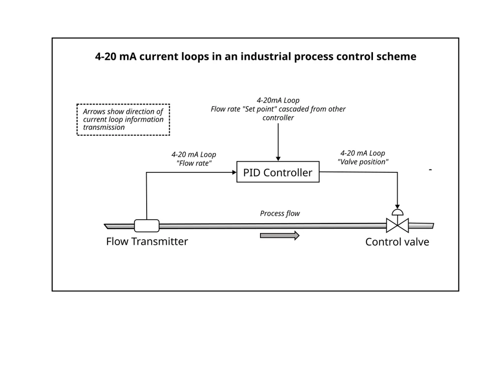
Why the signal starts at 4 mA, not 0 mA
The 4 mA lower endpoint is a live zero. At the bottom of the configured measurement range, current is still flowing, which allows a two-wire transmitter to remain powered and helps distinguish a valid zero-percent process value from a dead or open loop.
4 mA means
The process variable is at the configured lower range value, provided the instrument is healthy and correctly ranged.
0 mA usually means
The loop is open, power is missing, wiring is disconnected, a fuse is open, or the transmitter is otherwise unable to drive the loop.
Do not treat every value below 4 mA or above 20 mA as the same fault. Smart transmitters can intentionally drive defined underrange, overrange or alarm currents, and the exact thresholds depend on the device configuration and the standard it follows.
Two-wire loop wiring and active/passive inputs
A two-wire transmitter uses the loop both for operating power and for the measurement signal. A common external-supply arrangement is:
- Power-supply positive to transmitter positive.
- Transmitter negative to the positive/current terminal of the receiving analogue input.
- Analogue-input return/common back to power-supply negative.
Some PLC and DCS current inputs provide loop power themselves. Others are passive measurement inputs and require an external supply. Vendors also use the words active, passive, source and sink differently, so the wiring diagram for the exact input card and transmitter takes priority over terminology.
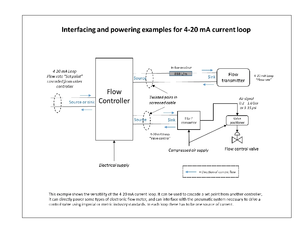
Loop voltage budget and maximum resistance
The supply must provide enough voltage for the transmitter plus every series voltage drop at the highest required loop current. If the available voltage is too low, the transmitter reaches its compliance limit and the current can clip below the correct value.
Example: 24 V supply
Assume a 24 V supply, a transmitter that requires at least 10 V, a 250 Ω receiving input, 50 Ω total cable resistance and a 2 V design margin. At 20 mA, the receiving input drops 5 V and the cable drops 1 V. The loop therefore needs 10 + 5 + 1 + 2 = 18 V, leaving 6 V of additional headroom.
Rearranging the voltage-budget equation gives the maximum permitted external resistance:
With 24 V, 10 V minimum transmitter voltage, 2 V margin and 20 mA maximum current, the available external resistance is 600 Ω. That 600 Ω must cover the receiving input, cable and any other series burden.
Scaling 4–20 mA into engineering units
For a linear transmitter, 4 mA corresponds to the lower range value (LRV) and 20 mA to the upper range value (URV). The usable measurement span is 16 mA.
Example: 0–10 bar pressure transmitter
At 12 mA, the signal is halfway through the 16 mA span. The corresponding process value is 5 bar. At 8 mA it is 2.5 bar; at 16 mA it is 7.5 bar.
| Current | Percent of span | 0–10 bar example |
|---|---|---|
| 4 mA | 0% | 0 bar |
| 8 mA | 25% | 2.5 bar |
| 12 mA | 50% | 5.0 bar |
| 16 mA | 75% | 7.5 bar |
| 20 mA | 100% | 10.0 bar |
NAMUR NE 43 fault and out-of-range currents
For devices configured to NAMUR NE 43, 4–20 mA remains the nominal measuring span. Values just outside it can indicate underrange or overrange rather than device failure: commonly used range limits are 3.8 mA and 20.5 mA, while failure alarm currents are driven to ≤ 3.6 mA or ≥ 21.0 mA.
Currents from above 3.6 mA to 3.8 mA, and from above 20.5 mA to below 21.0 mA, lie between the nominal range limits and the failure-alarm thresholds. PLC thresholds should therefore match the transmitter documentation and configured alarm settings.
Troubleshooting a 4–20 mA loop
Work from the electrical loop outward. First determine whether the problem is absence of loop power, inability to drive the required current, incorrect scaling, or a disagreement between the measured current and the PLC value.
- Verify loop power. Measure the DC supply and confirm that the transmitter sees enough terminal voltage while the loop is operating.
- Measure the actual current. A conventional multimeter must be inserted in series, which opens the loop during connection. A suitable mA process clamp can measure loop current without breaking the circuit.
- Compare field current with the PLC reading. If the measured mA value is correct but the PLC engineering value is wrong, check input configuration, raw scaling, LRV/URV and channel type.
- Check the voltage budget at high current. A loop that works near 4 mA but cannot reach 20 mA often has insufficient supply voltage or excessive series burden.
- Inspect wiring and terminals. Look for open conductors, reversed polarity, loose terminals, unintended grounds, barrier/isolator voltage drop and corrosion.
- Check transmitter diagnostics. If the current is intentionally below 4 mA or above 20 mA, determine whether the device is signalling underrange, overrange or an NE 43 alarm.
| Symptom | Likely checks |
|---|---|
| 0 mA | Power supply, fuse, open circuit, disconnected return, failed transmitter. |
| Stable but wrong mA | Sensor calibration, transmitter range, process condition, source simulation. |
| Correct mA, wrong PLC value | Channel configured for current, raw-count scaling, LRV/URV, input range. |
| Cannot reach 20 mA | Supply voltage, transmitter compliance, input burden, cable resistance, series devices. |
| Unstable current | Loose connections, supply instability, electrical interference, grounding/shielding practice, transmitter fault. |
Advantages and limitations of 4–20 mA
Advantages
- Good immunity to induced voltage noise in industrial environments.
- Long cable runs are practical when the loop voltage budget is adequate.
- Live zero helps distinguish a valid low reading from a dead loop.
- Two-wire transmitters can obtain operating power from the same loop.
- Broad compatibility across transmitters, PLCs, DCS systems and indicators.
Limitations
- Each conventional loop normally represents one process variable.
- Every series device consumes part of the available voltage budget.
- Analogue current alone does not carry rich device diagnostics.
- An incorrect active/passive loop-power arrangement can prevent the loop from operating.
- HART can add digital communication, but it has its own loop requirements.
For short, electrically quiet runs where both devices are designed for voltage signals, a 0–10 V interface can be simpler. For industrial field instrumentation, current loops are usually preferred when distance, noise immunity and live-zero diagnostics matter.