
4–20 mA vs 0–10 V: Comparison, Wiring & Selection
4–20 mA carries the process value as current through a series loop; 0–10 V carries it as a voltage measured against a reference. A 4–20 mA loop is often preferred for long field runs because series resistance mainly consumes loop voltage instead of directly changing the signal current. For short, controlled runs to a compatible high-impedance input, 0–10 V is often simpler to implement.
Neither interface guarantees better accuracy. Transmitter performance, the receiving input, wiring, grounding, interference and scaling all contribute to the final measurement error.
Match the sensor output to the analogue input before wiring. A 4–20 mA output needs a current input or a permitted shunt or converter; a 0–10 V output needs a voltage input or suitable conversion hardware.
What is the difference between 4–20 mA and 0–10 V?
Both interfaces can represent the same process value. The difference is what the receiver measures: current flowing through a 4–20 mA series loop, or voltage between the signal and reference terminals of a 0–10 V interface.
4–20 mA · current
The same loop current flows through the series path, provided the transmitter has enough supply voltage to overcome its own minimum operating voltage, the receiver burden and cable resistance.
- 4 mA normally represents the lower range value.
- 20 mA normally represents the upper range value.
- The 4 mA live zero can make loss of loop current distinguishable from a valid process zero.
0–10 V · voltage
The receiver measures voltage between the signal conductor and its reference terminal. Source impedance, input impedance, cable resistance and differences between reference potentials can change the voltage seen at the input.
- 0 V normally represents the lower range value.
- 10 V normally represents the upper range value.
- A valid 0 V reading and some wiring or power faults can look the same without separate diagnostics.
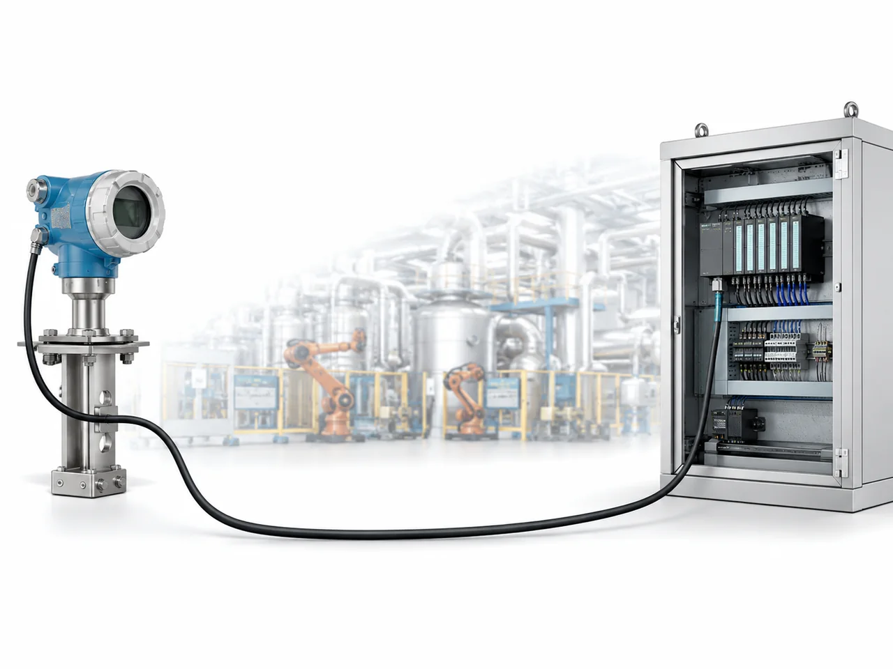
Current-loop wiring and voltage-output wiring are not interchangeable
A conventional two-wire 4–20 mA transmitter can take operating power from the same loop that carries the measurement. Many 0–10 V sensors instead use separate supply and signal conductors, commonly a three-wire arrangement. Four-wire transmitters and isolated interfaces also exist, so the conductor count does not identify the signal type.
Cable resistance, loading and electrical noise
A current loop regulates current, so ordinary series cable resistance does not directly create a proportional signal error while the transmitter remains within its available voltage budget. The resistance still matters because it consumes voltage at 20 mA. If the available supply voltage is insufficient, the transmitter can no longer maintain the commanded current.
A 0–10 V source behaves differently. The receiving input should have sufficiently high impedance relative to the sensor output impedance and cable resistance. Otherwise the source, wiring and input form a voltage divider and the voltage at the PLC can be lower than the voltage at the sensor.
For 0–10 V, usable cable length depends on the source, receiver, cable resistance, installation environment and required accuracy.
Why the 4 mA live zero matters
In a normally scaled 4–20 mA loop, 4 mA represents the valid lower range value, while loss of loop power or an open circuit can drive current toward 0 mA. That separation gives the receiving system a way to distinguish many electrical failures from a genuine process value at the bottom of range. A standard 0–10 V signal does not provide the same distinction because 0 V is itself a valid lower-range signal.
Some 4–20 mA transmitters and control systems also use defined under-range and over-range currents for diagnostics. If NAMUR NE 43 behaviour is required, use the range and alarm limits specified for the actual transmitter and receiver; not every 4–20 mA device implements NE 43 fault signalling.
Both signals use the same linear scaling principle
For a linear transmitter, the electrical signal is first normalised within its electrical range and then mapped to the engineering range. The difference is only the electrical lower and upper endpoints.
| Process position | 4–20 mA | 0–10 V | Example 0–100 bar |
|---|---|---|---|
| 0% | 4 mA | 0 V | 0 bar |
| 25% | 8 mA | 2.5 V | 25 bar |
| 50% | 12 mA | 5 V | 50 bar |
| 75% | 16 mA | 7.5 V | 75 bar |
| 100% | 20 mA | 10 V | 100 bar |
Current versus voltage does not determine total channel accuracy. Error can come from the sensor or transmitter, analogue output, wiring, input conversion, calibration and scaling.
Match the output to the analogue-input mode
Many PLC analogue modules can be configured for current or voltage, but the electrical input path is different. Select the correct channel mode, terminals and range before connecting the field signal. A software scaling change does not turn a voltage input into a current input or vice versa.
| Check | 4–20 mA | 0–10 V |
|---|---|---|
| Input mode | Current range selected | Voltage range selected |
| Connection | Series current path | Signal plus reference/common |
| Receiver electrical limit | Input burden / loop voltage drop | Input impedance / common-mode range |
| Field power | Confirm active/passive loop arrangement | Confirm sensor supply and reference |
| Scaling | 4 mA = LRV; 20 mA = URV | 0 V = LRV; 10 V = URV |
Can 4–20 mA be converted to a voltage?
A precision shunt resistor can convert loop current into a voltage when the resulting burden is permitted by the loop. For example, 4–20 mA through 250 Ω produces 1–5 V; through 500 Ω it produces 2–10 V. The added resistance consumes loop voltage, so it must be included in the voltage budget.
That is not the same as converting a 0–10 V source into a proper 4–20 mA transmitter. Voltage-to-current conversion normally requires an active signal conditioner or transmitter, especially when isolation, diagnostics or a defined current-loop compliance range are required.
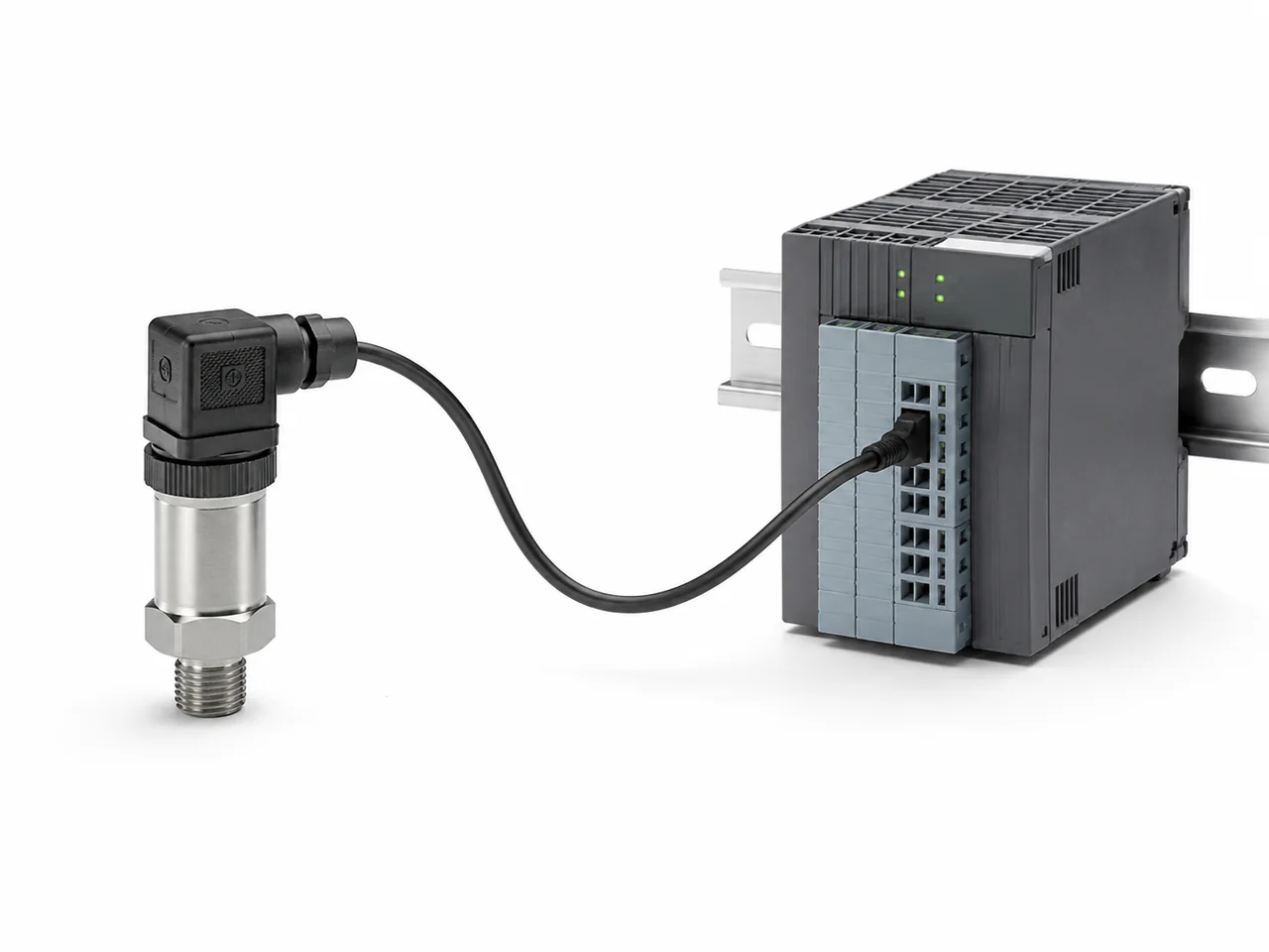
When should you choose 4–20 mA or 0–10 V?
Choose 4–20 mA when the cable run is long, loop-powered two-wire operation is useful, or a live zero helps distinguish loss of signal from a valid low process value. Choose 0–10 V for short, well-controlled runs where the sensor and controller share a suitable reference and the receiving input is designed for a voltage signal.
| Application factor | Usually favours 4–20 mA | Usually favours 0–10 V |
|---|---|---|
| Long field cable | Yes, if loop voltage budget remains adequate | Possible, but loading, reference and interference need closer checking |
| Interference / difficult routing | Often preferred, but routing and shielding still matter | Suitable where interference and the reference are well controlled |
| Wire-break visibility | Live zero provides a useful diagnostic distinction | 0 V is also a valid process value |
| Two-wire loop power | Common and practical | Normally requires separate power conductors |
| Short local connection | Still suitable | Often simple and convenient |
| Parallel voltage measurement | Current measurement normally requires series access or a test point | Voltage can usually be checked in parallel with a high-impedance meter |
Troubleshooting 4–20 mA and 0–10 V signals
Start by finding where the value changes: at the source, along the wiring or at the receiving input. Measure the signal at suitable test points, then compare it with the PLC raw value and the expected process value.
- Confirm the configured signal type. Verify current versus voltage mode, range and the correct input terminals.
- Check power and references. For 4–20 mA, verify loop power and polarity. For 0–10 V, verify sensor power and the intended signal reference/common.
- Measure the signal safely. Voltage is normally measured in parallel. Current is measured in series or at a manufacturer-provided current test point/shunt.
- Check electrical limits. Calculate loop voltage budget for 4–20 mA; check output drive and input impedance for 0–10 V.
- Compare both ends of the cable. A correct source value but wrong PLC value points toward wiring, reference, loading, interference or input configuration.
- Verify scaling last. Once the electrical signal is correct, confirm raw-count conversion, engineering endpoints and any configured fault handling.
| Symptom | Likely checks |
|---|---|
| 4–20 mA stuck near 0 mA | Open loop, no loop supply, reversed polarity, wiring fault or failed transmitter. |
| 4–20 mA cannot reach full scale | Insufficient supply/compliance voltage, excessive burden or cable resistance, transmitter limit. |
| 0–10 V lower at PLC than at sensor | Loading, cable/reference drop, shared common current, input impedance or wiring resistance. |
| 0–10 V noisy or drifting | Reference-potential difference, routing, shielding, grounding, interference or unstable source. |
| Correct electrical value, wrong engineering value | PLC input range, raw scaling, LRV/URV, data type or channel configuration. |
| Replacement sensor does not work | Output type differs, current/voltage input mismatch, active/passive loop mismatch, pinout or supply range. |