
2-Wire vs 3-Wire vs 4-Wire Sensors: Wiring & PLC Inputs
In industrial automation, 2-wire, 3-wire and 4-wire usually describe how a sensor's conductors are assigned to power and output, but the conductor count does not identify the electrical interface. A 2-wire device may be a series switching sensor or a loop-powered 4–20 mA transmitter; a 3-wire device commonly uses +V, 0 V and one output; a 4-wire device can use the extra conductor for a second output or a separate signal return.
Identify the function of every terminal before wiring. The same number of conductors can represent different electrical interfaces, and RTD 2/3/4-wire terminology describes lead-resistance compensation rather than the power/output arrangements used by active industrial sensors.
Do not identify a sensor from wire count or colour alone. Confirm the supply terminals, output type, common or return, PLC input requirements and the exact manufacturer's wiring diagram before energising the circuit.
What 2-wire, 3-wire and 4-wire actually mean
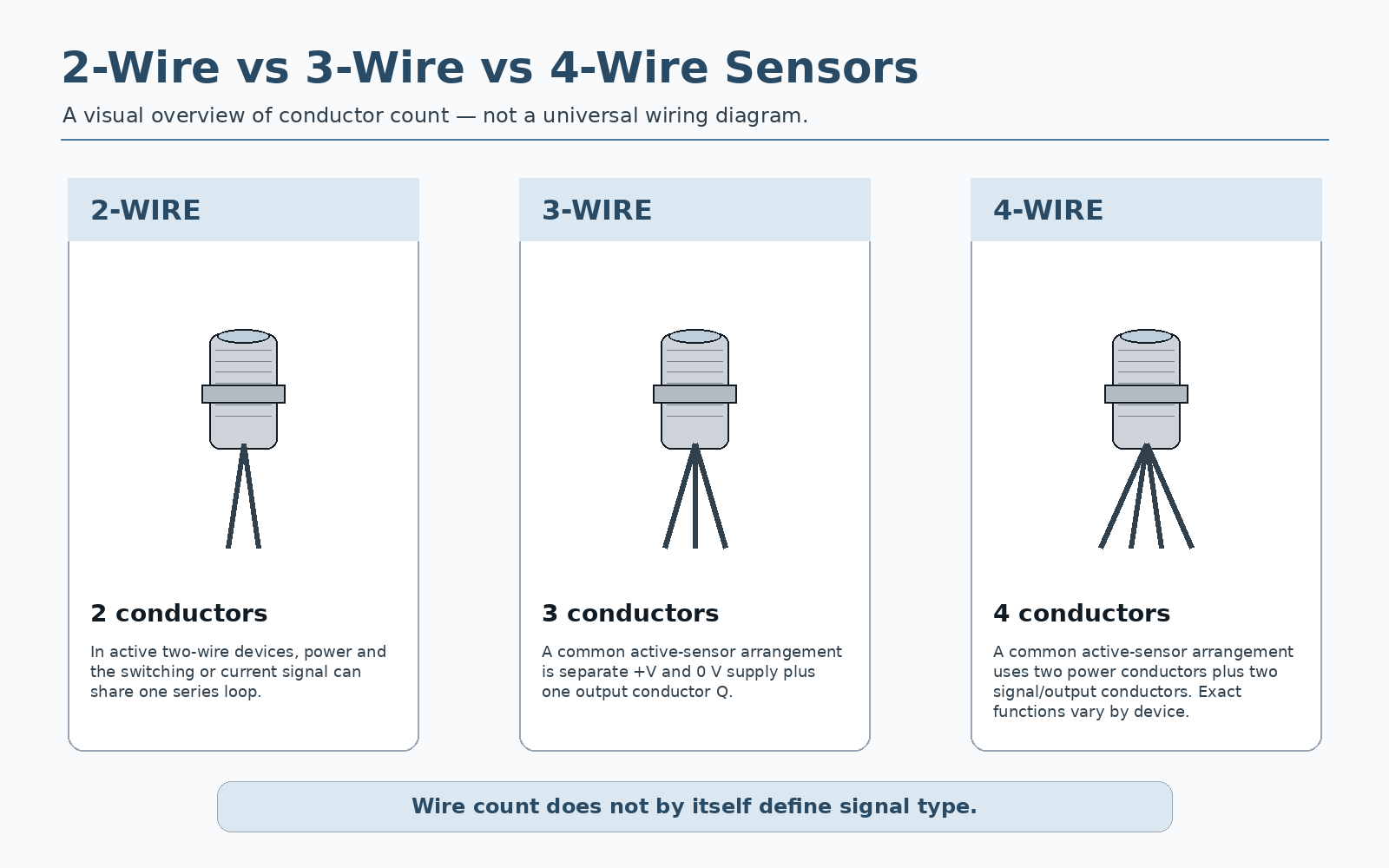
Conductor count describes the number of electrical connections leaving the device. The next step is to identify each conductor's function: supply, return/common, switching output, analogue output, signal return or another assigned function.
Power and signal may share the same current path, as in a loop-powered transmitter, or the sensor may act as an electronic switch connected in series with the load.
Two conductors normally power the electronics and a third carries one output. Common examples are DC PNP/NPN switching sensors and voltage-output sensors.
Two conductors may power the device while the other two form a signal pair, or the fourth conductor may provide a second switching output. The wiring diagram defines the assignment.
Two-wire sensors: one pair can serve very different circuits
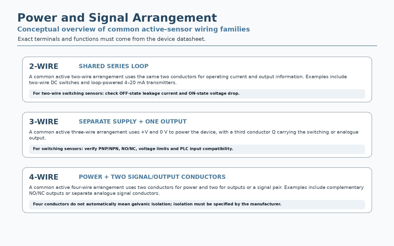
An active two-wire industrial sensor can use the same pair for operating power and signal current. Two cases are especially easy to confuse: a loop-powered analogue transmitter regulates current in a measurement loop, while a two-wire switching sensor operates in series with its load or PLC input.
The transmitter takes operating power from the loop and regulates that same loop current to represent the process value. Supply voltage, input burden and all series drops must fit the 4–20 mA loop voltage budget.
The sensor and load share a series circuit. Because the sensor electronics still need power, an electronic two-wire switch can have OFF-state leakage current and ON-state residual voltage that a mechanical contact would not have.
For a switching sensor, check the input's required ON current, maximum OFF current and the sensor's residual voltage. A sensitive PLC input can remain partially energised by leakage current, while a high-burden load can leave too little voltage across the sensor for reliable operation.
Three-wire sensors: separate supply and one output
A common three-wire DC arrangement is positive supply, 0 V/common and one signal output. The sensor is powered independently of the output state.
With a discrete output, the third wire is commonly PNP or NPN. A PNP output sources current into the receiving input when ON; an NPN output sinks current toward 0 V. A three-wire analogue sensor may instead use the third conductor for a 0–10 V output or a current output referenced to the supply common.
Four-wire sensors: the fourth conductor has no universal function
Four conductors support several circuit arrangements, so “4-wire” is ambiguous without the wiring diagram. Common patterns include separate power and signal pairs, two complementary switching outputs, or a second independently configurable output.
Some four-wire transmitters provide galvanic isolation between power and signal circuits, but four conductors do not prove isolation. Other four-wire devices share an internal common. If isolation, common-mode voltage or grounding is important, check the electrical isolation specification rather than inferring it from conductor count.
A four-wire proximity sensor may simply provide both NO and NC outputs. That device is electrically very different from a four-wire analogue transmitter with a separate signal return, even though both have four conductors.
Matching the sensor wiring to a PLC or controller input
Start at the receiving module. Identify whether the channel is a digital input, current input, voltage input, counter/frequency input or a configurable universal input. Then trace the complete current or voltage path back through the sensor.
| Sensor arrangement | Typical interface | Critical PLC-side check |
|---|---|---|
| 2-wire electronic switch | Series DC or AC switching circuit | Input/load current, OFF-state leakage current, ON-state residual voltage and polarity where applicable. |
| 2-wire 4–20 mA | Loop-powered analogue current | Loop supply, active/passive input, polarity and voltage budget. |
| 3-wire PNP/NPN | DC digital input | Sourcing/sinking compatibility, DI common and ON/OFF thresholds. |
| 3-wire voltage output | 0–10 V / other voltage input | Signal reference, input impedance and common-mode limits. |
| 4-wire device | Two outputs or separate power/signal | Function of both extra terminals; never assume isolation or complementary logic. |
Software inversion cannot fix an electrically incompatible input. For example, changing a PLC tag from normally open to normally closed does not make an NPN input circuit accept a PNP sensor if the required current path is absent.
Wire colours and connector pins are clues, not proof
Many industrial DC sensors use brown for positive supply, blue for 0 V, black for the primary output and white for a second output or auxiliary function. On many M12 sensors, these functions also appear on familiar pin positions. These conventions are useful during commissioning, but they are not a substitute for the exact product wiring diagram.
Connector pin count is also different from the number of electrically used conductors. A sensor may use a four-pin M12 connector but only three pins for power and one switching output. Another device with the same connector shell may use all four pins for two outputs.
2-wire, 3-wire and 4-wire RTDs mean something different
When the same terminology is used for Pt100 or Pt1000 RTDs, the extra wires are used primarily to compensate for lead resistance. This is a resistance-measurement topology, not the same classification used for powered PNP/NPN sensors or externally powered analogue transmitters.
The measuring instrument sees the RTD element plus the resistance of both leads. Lead resistance therefore adds directly to the measured resistance.
The measuring circuit compensates for lead resistance by using the third conductor, typically assuming the corresponding lead resistances are equal or closely matched.
Separate current and voltage-sense connections allow a Kelvin measurement that largely removes lead resistance from the result.
Do not apply RTD 2/3/4-wire rules to powered sensors. In an RTD, the extra leads support lead-resistance compensation; in an active sensor, extra conductors may carry power, outputs or a signal reference.
Replacing or troubleshooting 2-wire, 3-wire and 4-wire sensors
A replacement sensor must match the electrical interface, not merely the number of wires. Check supply range, output type, polarity, NO/NC or output logic, analogue range, current capability, leakage current, residual voltage, connector pinout and the receiving PLC input before treating two devices as interchangeable.
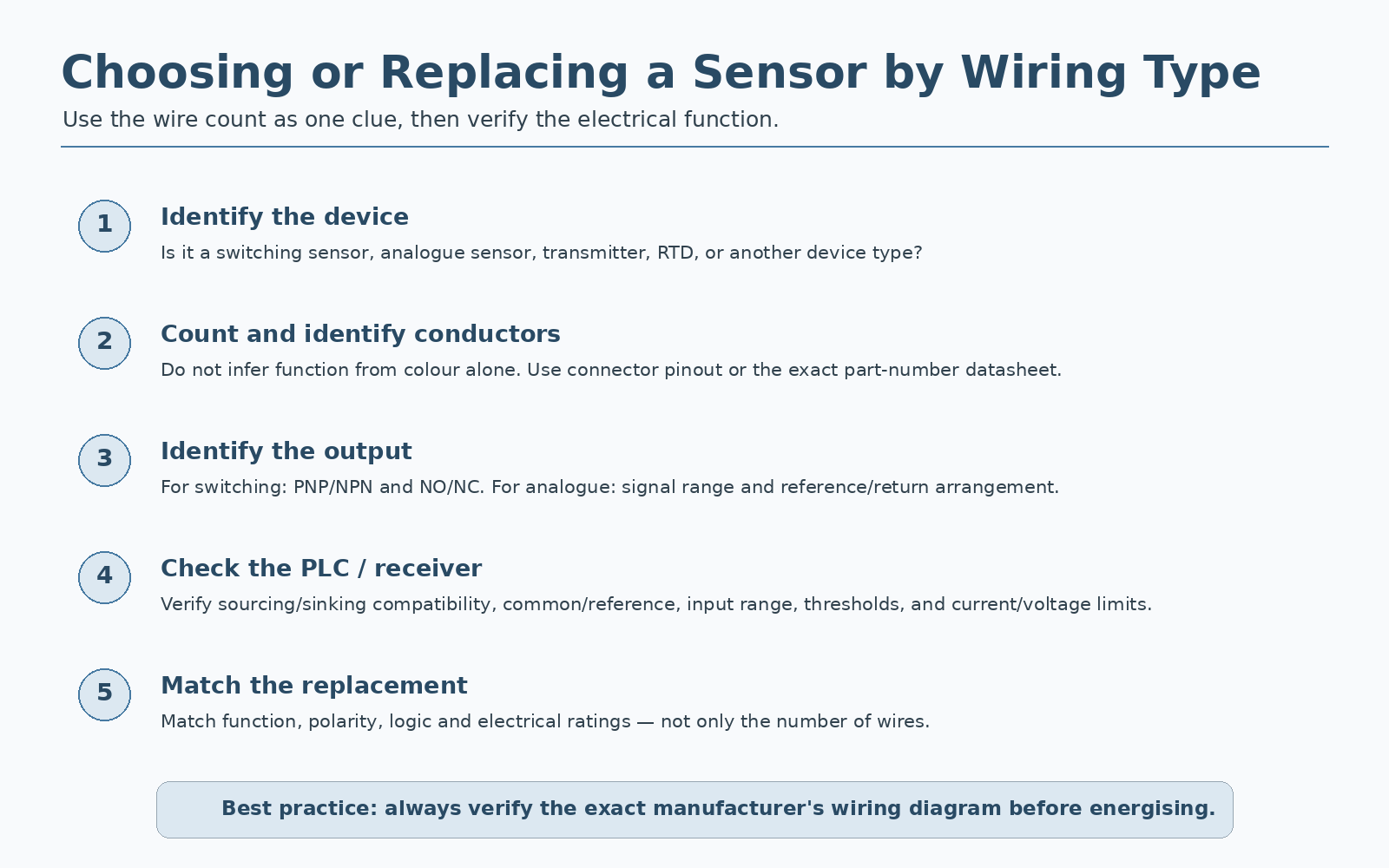
- Read the exact part number. Identify whether the device is a switch, analogue transmitter, pulse source, RTD or another sensor type.
- Label every conductor by function. Mark supply, return/common, primary output, second output or signal return from the manufacturer's diagram.
- Confirm the PLC channel type. Check digital versus analogue, current versus voltage, PNP/NPN current path, active/passive loop power and input thresholds.
- Measure before reconnecting. Verify supply voltage and reference potentials; for an output conductor, measure it using the reference specified for that output.
- Check electrical limits. Include output current, leakage, residual voltage, load impedance, cable resistance and any external barriers or isolators.
- Test the complete state change. Confirm both the sensor indication and the actual PLC value or input state rather than relying on the sensor LED alone.
| Symptom | Likely checks |
|---|---|
| Same wire count, replacement does not work | Different PNP/NPN output type, signal type, pinout, NO/NC logic or supply range. |
| 2-wire input never turns fully OFF | Sensor leakage current versus PLC OFF threshold or load impedance. |
| 2-wire device cannot turn load fully ON | Residual voltage, insufficient load current or wrong series connection. |
| 3-wire sensor LED changes, PLC does not | PNP/NPN compatibility, missing common, output conductor, threshold or damaged input. |
| 4-wire device behaves unexpectedly | Function of fourth conductor, complementary versus independent outputs, shared versus isolated return. |
| RTD reading shifts with cable length | RTD input configured for the correct 2/3/4-wire mode and lead-resistance compensation. |