
Inductive vs Capacitive Proximity Sensors
Use an inductive proximity sensor for metal targets when short-range, repeatable detection is required around machinery. Use a capacitive proximity sensor when the target itself may be plastic, glass, liquid, powder, wood or another non-metallic material, including some through-wall level applications.
The housings and electrical outputs can look similar, but the sensing principles are different. The practical choice depends on target material, operating gap, mounting and the conditions around the sensing face.
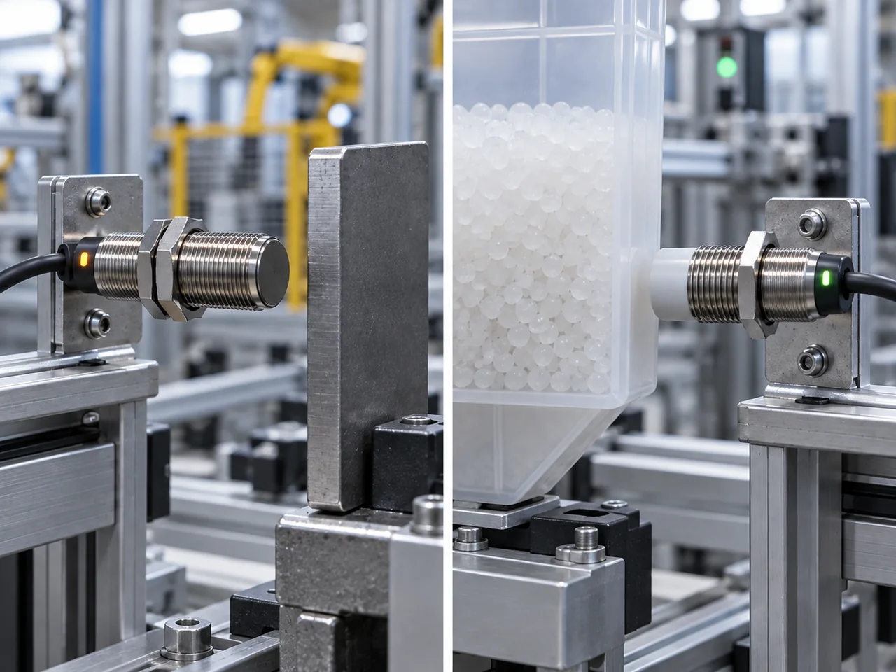
Metal machine target: usually inductive. Plastic, liquid, powder or another non-metallic target: consider capacitive. Select the sensing principle first, then choose the electrical output and housing.
Inductive and capacitive sensing: the core difference
Inductive and capacitive proximity sensors both detect a nearby target without mechanical contact, but they react to different physical effects. An inductive sensor creates an alternating electromagnetic field and detects the losses produced by eddy currents in a conductive target. A capacitive sensor responds to a change in capacitance at its sensing electrode when material enters the electric field.
| Selection point | Inductive proximity sensor | Capacitive proximity sensor |
|---|---|---|
| Detectable target | Metals only, including ferrous and non-ferrous metals when the model is suitable. | Metals plus many non-metals: plastic, glass, paper, wood, powders and liquids. |
| Physical principle | Electromagnetic field and eddy-current losses in the target. | Change in electric-field capacitance caused by target permittivity and conductivity. |
| Best suited to | Stable metal detection around oil, dirt and machine hardware; high switching rates are common. | Detects non-metal products and can sometimes sense product through a plastic or glass wall. |
| Main variable affecting range | Target metal, target size, sensor diameter and flush/non-flush mounting. | Target dielectric properties, amount of material, sensitivity setting and nearby material. |
| Main limitation | Reduced range on some non-ferrous metals or incorrect mounting near metal. | Moisture, residue or changing background material can shift the switching threshold. |
| Typical jobs | Metal part presence, end position, gear/tooth counting, machine fixtures. | Bottle presence, liquid level, pellets, powders, plastics and product presence through non-metal walls. |
Inductive sensing principle
The sensing coil at the active face is driven by an oscillator. A metal target entering the electromagnetic field develops eddy currents. Those currents remove energy from the oscillator, and the sensor electronics detect the resulting change and switch the output.
Suitable targets
Inductive sensors are intended for conductive metal targets. Published sensing distances are normally measured with a defined reference target under specified test conditions, so the usable distance on a real machine part can change with alloy, thickness and target area.
Unsuitable targets
Plastic, paper, glass, dry bulk material and most liquids do not create the eddy-current effect required by a normal inductive sensor. If the object itself is non-metallic, use another sensing principle or add a metal flag when the machine design permits it.
Non-ferrous metals can be detected, but a conventional inductive sensor may have a shorter usable distance for aluminium, brass or copper than for mild steel. The correction factor is model-dependent. Factor-1 inductive designs are available when similar operating distance is required across different metals.
| Target material | Typical factor vs steel | Example if rated steel range is 10 mm |
|---|---|---|
| Mild steel / Fe360 | 1.0 | 10 mm |
| Stainless steel | 0.60–1.00 | about 6–10 mm |
| Aluminium | 0.30–0.45 | about 3.0–4.5 mm |
| Brass | 0.35–0.50 | about 3.5–5.0 mm |
| Copper | 0.25–0.45 | about 2.5–4.5 mm |
These are representative conventional-sensor values, not universal constants. The actual reduction factor depends on sensor design, shielding and target geometry. A Factor-1 sensor is designed to keep the reduction factor at or near 1 across common metals.
Capacitive sensing principle
A capacitive sensor uses an electrode at the sensing face and monitors the electrical capacitance of the surrounding field. When a target approaches, its conductivity and relative permittivity change that capacitance. The oscillator or evaluation circuit detects the change and switches the output when the configured threshold is crossed.
Used for point-level detection and, where the wall and product allow it, for sensing liquid through a non-metallic tank wall.
Suitable for granular or powdered product when there is no metal target to sense.
Suitable for many dielectric materials that a standard inductive sensor will not detect.
Can also detect metal, but inductive sensing is usually preferable when the target is metal only because it is more selective and less affected by nearby dielectric material.
Capacitive sensing depends strongly on the target and its surroundings. Water-rich material generally produces a larger capacitance change than dry low-permittivity material. A sensitivity control or teach function is therefore common, but the correct setting is not simply “maximum sensitivity”. Excess sensitivity reduces margin against deposits, moisture or nearby structure.
| Material | Approx. relative permittivity, εr | What it means for sensing |
|---|---|---|
| Air | ≈ 1.0 | Reference background; very small dielectric effect. |
| PTFE / low-permittivity plastics | ≈ 2.0–2.4 | Closer to air, so target volume and distance matter more. |
| Common plastics | ≈ 2–4 | Often detectable at short range, but geometry and wall thickness matter. |
| Ethanol | ≈ 24 | Produces a much larger dielectric change than most dry plastics. |
| Water at about 20 °C | ≈ 80 | Strong dielectric response; moisture and condensation can also shift the threshold. |
Relative permittivity varies with material composition, temperature and measurement frequency. These values explain the trend; they are not calibration data for a proximity sensor.
Sensing distance: which technology reaches farther?
Neither technology has a consistently longer sensing distance. The usable distance depends on sensor geometry, mounting class and the actual target. A large capacitive sensor may reach farther than a standard inductive model, while a long-range inductive sensor can exceed a smaller capacitive device. Compare catalogue distance only after checking the target material and mounting conditions.
For inductive sensors, flush (shielded/embeddable) and non-flush (unshielded/non-embeddable) construction also matters. Non-flush models can often provide more range but require a metal-free zone around the active face. Capacitive models also have mounting constraints because surrounding material changes the electric field.
Behaviour in dirt, moisture and changing product conditions
For a metal target in machinery, inductive sensing is usually more selective because oil, dust and nearby plastic are not intended targets. A capacitive sensor reacts to changes in the dielectric field, so water films, deposits or changing product around the sensing face can shift the switching point.
| Condition | Inductive | Capacitive |
|---|---|---|
| Oil or dust on target | Usually little effect on metal detection unless build-up contains enough metal or changes the mechanical gap. | Can influence the field when the contamination has a significant dielectric effect. |
| Water film / condensation | Generally not the sensing target. | Can shift threshold because water has a strong dielectric effect. |
| Nearby metal bracket | Critical to flush/non-flush mounting and free-zone requirements. | Nearby material can also change the field; follow the mounting instructions. |
| Changing product recipe | Not relevant if the actuator remains the same metal target. | May change sensitivity when density, moisture or composition changes. |
| Optical contamination | No lens or line-of-sight requirement. | No optical alignment, but surface contamination can still affect capacitance. |
Selection: when to use each sensor
Choose inductive when
- The target itself is metal.
- Fast, repeatable part-presence or end-position detection is required.
- The sensor sits in an oily, dusty or mechanically harsh machine environment.
- You want the sensor to ignore plastic, glass, liquid or product around the metal target.
- A metal flag can be added to the moving part more reliably than sensing the process material directly.
Choose capacitive when
- The target is plastic, glass, paper, wood, powder, pellets or liquid.
- Product level must be detected without a metal float or mechanical switch.
- Detection through a suitable plastic or glass wall is useful.
- The material itself is the quantity of interest rather than a metal machine component.
- The installation can be commissioned with realistic product, moisture and deposit conditions.
| Application | Typical choice | Why |
|---|---|---|
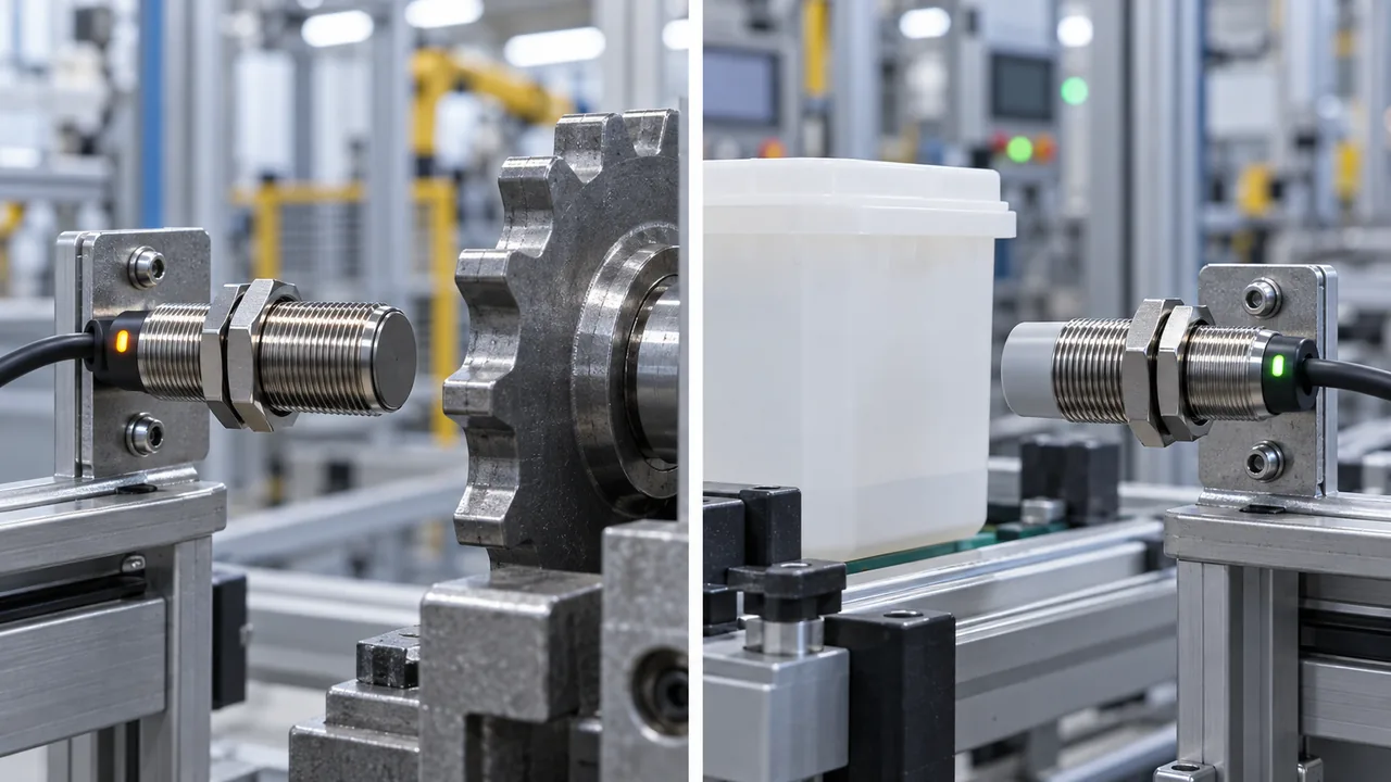
| Detect steel gear tooth | Inductive | Direct, selective metal detection with fast switching. |
| Verify aluminium can is present | Inductive | Metal target; verify the model’s range for aluminium. |
| Detect plastic bottle | Capacitive or photoelectric | A normal inductive sensor cannot detect the plastic body. |
| High/low liquid level through a plastic wall | Capacitive | The field can respond to the liquid through a suitable non-metallic barrier. |
| Powder level in hopper | Capacitive | Bulk dielectric material can be sensed without a mechanical float. |
| Machine slide end position | Inductive | A metal flag or slide body gives a robust actuator independent of colour or transparency. |
Quick sensor selector
Use this as a first-pass screening tool. It does not replace the sensing-distance, mounting and environmental limits in the exact sensor datasheet.
One-page reference with technology choice, metal correction factors, relative permittivity and installation checks.
Mounting and commissioning
- Define the real target. Record material, dimensions, wall thickness, moisture range and the closest background material.
- Choose the sensing principle before the output type. Target physics determines inductive versus capacitive; PNP/NPN is chosen afterward to match the controller.
- Check the mounting class. Follow flush/non-flush clearance and sensor-to-sensor spacing for the exact model.
- Set an operating distance with margin. Do not commission at the catalogue maximum.
- Test worst-case material. For inductive sensing, test the actual alloy and smallest target. For capacitive sensing, test the driest/wettest or lowest/highest density product expected.
- Test expected contamination. Check likely oil, dust, condensation or residue before accepting the switching threshold.
- Verify the PLC input separately. A sensor LED changing state does not prove PNP/NPN compatibility or correct terminal wiring.
Common engineering questions
Can a capacitive proximity sensor detect metal?
Yes. Metal causes a strong capacitance change, so capacitive sensors can detect it. That does not make capacitive the best default for metal-only applications; inductive sensing is normally more selective because it is designed specifically around conductive targets.
Can an inductive sensor detect aluminium or copper?
Yes, if the selected inductive sensor supports the target and the operating distance is set correctly. Standard models often have a reduced range for some non-ferrous metals compared with steel. Use the model-specific reduction data or a factor-1 design when equal-metal range is required.
Can a capacitive sensor detect liquid through a plastic tank?
Often, yes, when the wall is non-metallic and thin enough for the field to respond to the material behind it. The installation still needs testing because wall thickness, deposits, liquid properties and sensor sensitivity all affect the switching margin.
Which is better for dirty industrial machinery?
For a metal target, inductive is usually the better starting point. Oil and dust normally have little effect on metal detection, while moisture or deposits near a capacitive sensing face can shift its switching threshold.
Which is faster for high-speed counting?
Inductive sensors are commonly used for fast metal counting, and many industrial models are rated from hundreds of hertz into the kilohertz range. Check the switching frequency of the exact model against target size, speed and operating gap; the sensing principle by itself does not define the maximum count rate.
Are inductive and capacitive sensors wired differently?
Not necessarily. Both technologies can use common industrial interfaces such as 10–30 V DC, PNP or NPN transistor outputs and NO or NC logic. Always wire from the actual model diagram rather than assuming the sensing principle determines the output.