
Sensor Signal Conditioning: From Sensor Output to Usable Measurement
Sensor signal conditioning is the set of electrical and computational functions that make a sensor output suitable for accurate acquisition, transmission or control. Depending on the sensor, conditioning can include excitation, amplification, attenuation, filtering, isolation, linearisation, cold-junction compensation, bridge completion, level shifting and matching the signal to the usable input range of an ADC, PLC or DAQ system.
The correct conditioner preserves the information produced by the sensor while rejecting interference and preventing the next stage from being overdriven, under-ranged or exposed to unsafe common-mode voltage. The required functions depend on the sensor technology, cable run, bandwidth, grounding scheme and receiving input.
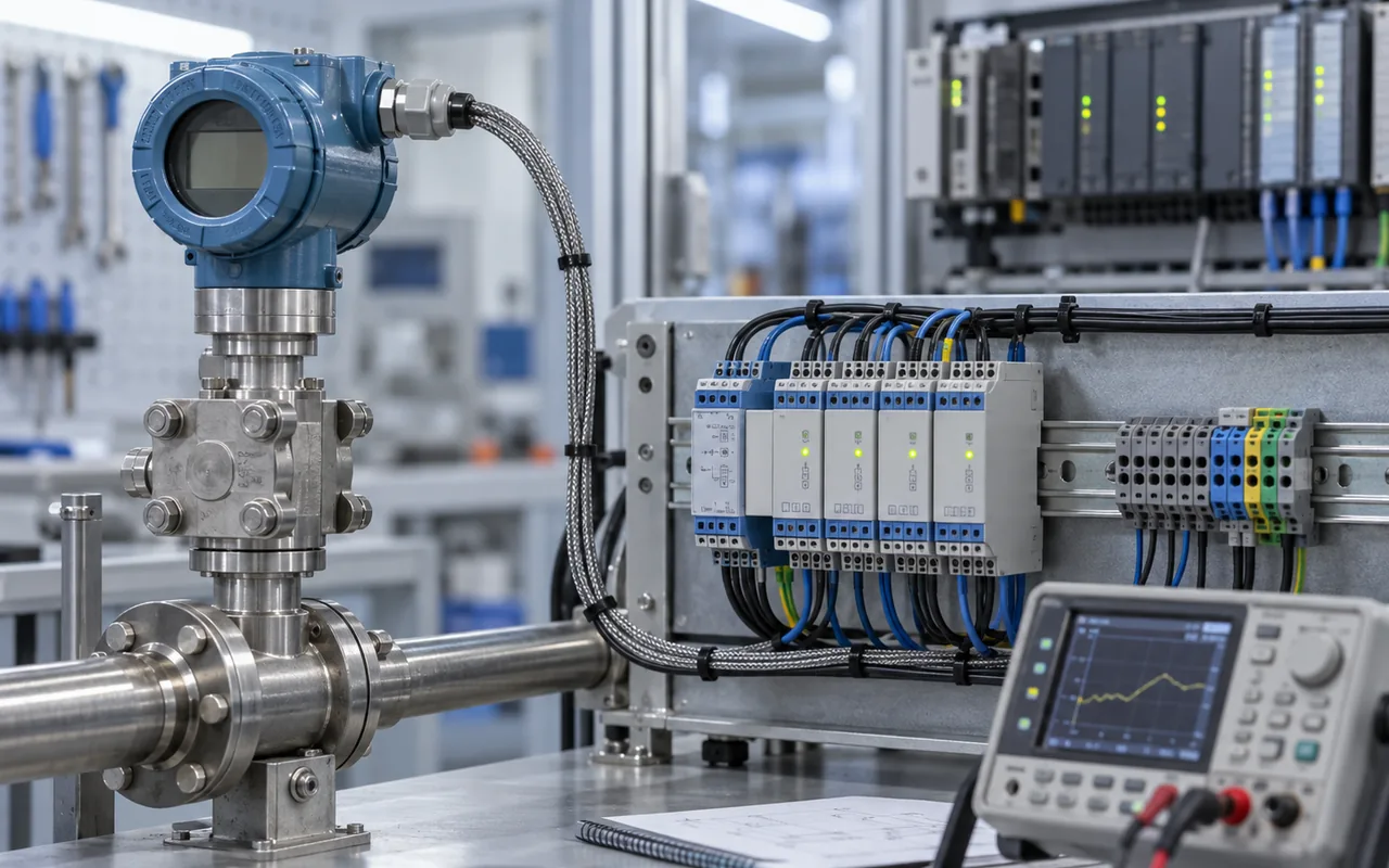
Condition only what the measurement needs. Choose gain from the real signal range, set bandwidth from the required process dynamics, isolate where ground potential or safety demands it, and verify the complete sensor-to-ADC path rather than treating the conditioner as a generic box.
Amplification, filtering, isolation and excitation solve different signal problems
The main purpose of signal conditioning is not simply to make a signal larger. It is to present the downstream measurement stage with a signal that is electrically compatible, within range, sufficiently quiet, correctly referenced and representative of the measurand over the required bandwidth.
| Function | Why it is used | Typical application |
|---|---|---|
| Amplification | Raises low-level sensor signals so more of the ADC or analogue-input range is used. | Thermocouples, strain bridges, load cells, low-level mV sensors. |
| Attenuation / level shifting | Reduces or offsets a signal so it remains inside the safe common-mode and input range of the receiving stage. | ±10 V sources into lower-voltage ADCs; bipolar signals into unipolar converters. |
| Input protection | Limits fault, surge or transient energy before it reaches precision analogue circuitry. | Long field wiring, inductive environments and exposed analogue inputs. |
| Filtering | Restricts measurement bandwidth and rejects unwanted noise or interference before digitisation. | Slow temperature, pressure and load measurements in electrically noisy plant environments. |
| Isolation | Breaks galvanic current paths and tolerates potential differences between field and control-side grounds. | Long cable runs, grounded thermocouples, remote transmitters and mixed-ground systems. |
| Excitation | Supplies a controlled voltage or current to passive sensors whose output depends on an applied source. | RTDs, thermistors, strain gauges, bridge pressure sensors. |
| Linearisation / compensation | Transforms a non-linear sensor relationship or compensates known dependencies. | Thermocouples, thermistors, RTDs, bridge sensors and temperature-compensated transducers. |
Use enough gain to exploit the converter range without clipping the worst-case signal
Low-level sensors waste resolution when their useful output occupies only a small fraction of the receiving input span. Gain can improve this by scaling the signal closer to the converter's full usable range, but the gain must include headroom for sensor tolerance, zero offset, overrange, common-mode voltage and any transient that the input must survive.
Example: 20 mV bridge output into ±10 V input
If the useful differential signal is only 0–20 mV while the input module spans 20 V peak-to-peak, direct connection uses only a very small part of the converter range. A low-noise instrumentation amplifier or dedicated bridge input can provide the required gain while rejecting common-mode voltage.
Why gain cannot fix a bad signal-to-noise ratio
An ideal amplifier multiplies the wanted signal and the noise already present at its input by the same factor. A 10 mV signal with 1 mV RMS of input-referred noise becomes about 1 V of signal and 100 mV RMS of the same noise at a gain of 100, so the input SNR itself has not improved.
Gain is still useful because a low-noise front end can make better use of the ADC or PLC input range and reduce the relative importance of noise added by later stages. Real SNR improvement comes from limiting bandwidth, filtering interference, using differential inputs and correct shielding, providing stable excitation and choosing a low-noise front end. Leave enough gain headroom for offset, interference and transients so the amplifier and converter do not clip.
Common-mode range matters as much as differential range
An instrumentation amplifier may see a small differential signal riding on a much larger common-mode voltage. The amplifier must remain within its specified input common-mode range and output swing at the chosen gain and supply voltage. High CMRR is valuable, but it is not a substitute for checking those operating limits.
Set the analogue bandwidth from the fastest real process information you need
Filtering attenuates out-of-band energy before it reaches the converter. In industrial measurement this improves noise performance, reduces interference and helps prevent higher-frequency content from aliasing into the sampled band. The trade-off is response time: a filter that is too aggressive can suppress a real transient or make a control loop appear slower than the process.
Passes slow process variation while attenuating higher-frequency noise. Common for temperature, pressure, level and static force measurement.
Targets narrow interference such as 50 or 60 Hz, but verify phase and settling behaviour if the measurement must respond quickly.
Limits analogue bandwidth before sampling so frequencies above the usable Nyquist band do not fold into the measurement spectrum.
Can further reduce noise after conversion, but cannot undo aliasing that occurred before the ADC.
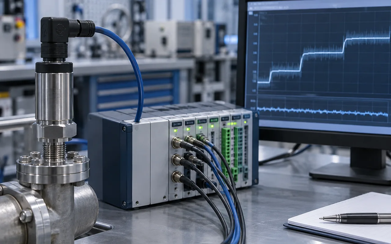
Isolation is used when the field signal and the receiving system cannot safely share the same electrical reference
Ground potential differences can drive unwanted current through signal conductors and cable shields. The resulting error may appear as an offset, mains-frequency interference, unstable readings or, in severe cases, damage. Galvanic isolation breaks the direct conductive path while transferring the measurement across an isolation barrier.
Isolation ratings must be read as complete safety and performance specifications: working voltage, test voltage, insulation coordination, surge environment, common-mode transient behaviour and applicable equipment standards are separate considerations. Do not treat a headline isolation voltage as permission to connect arbitrary hazardous potentials.
Thermocouples, RTDs, bridges and current loops need different conditioning
A sensor interface should be selected from the electrical behaviour of the sensor, not from the measurand name alone. A pressure measurement may come from an unconditioned millivolt bridge, a 0–10 V transmitter, a two-wire 4–20 mA transmitter or a digital device; each version imposes different requirements on the receiving input.
| Sensor / signal | Typical conditioning | Critical checks |
|---|---|---|
| Thermocouple | Low-noise amplification, filtering, cold-junction compensation, linearisation, open-sensor detection where required. | Thermocouple type, reference-junction accuracy, grounded vs ungrounded junction, common-mode range, cable alloy and polarity. |
| RTD | Stable current or voltage excitation, differential measurement, lead-resistance compensation, filtering and linearisation. | 2-/3-/4-wire topology, excitation self-heating, lead resistance, sensor standard and measurement current. |
| Thermistor | Excitation or divider network, range scaling, filtering and strong non-linear conversion to temperature. | Self-heating, resistance range, beta or Steinhart-Hart data and interchangeability tolerance. |
| Strain gauge / load cell | Bridge excitation, instrumentation amplification, filtering, bridge completion where needed, offset nulling and sometimes shunt calibration. | mV/V sensitivity, bridge resistance, excitation stability, remote sense, cable resistance and mechanical zero. |
| 0–10 V / ±10 V | Input protection, attenuation or level shifting if required, filtering and optional isolation. | Source impedance, receiving input impedance, common reference, cable routing, ground potential and allowable overvoltage. |
| 4–20 mA | Precision shunt or current input, loop supply when required, filtering, isolation and fault-range handling. | Loop voltage budget, shunt burden, two-/three-/four-wire device type, polarity and configured fault limits. |
The conditioner and converter must be designed as one signal chain
The final analogue stage has to drive the real input of the ADC or PLC module. Converter inputs can present switched-capacitor loading, finite source-impedance requirements, common-mode constraints and settling-time demands. A precision buffer or ADC driver may be needed even when the sensor signal appears to be at the correct voltage level.
- Match the span. Scale the expected normal and overrange signal to use the converter range without clipping.
- Check source impedance. Verify the maximum source resistance or acquisition-time requirement of the receiving input.
- Set the bandwidth. Place analogue filtering before the ADC and choose the sampling rate with enough anti-alias margin.
- Respect common-mode limits. Differential inputs still have finite common-mode ranges; isolation may be necessary if the field reference is remote.
- Include the reference. Converter reference noise and drift can directly affect ratiometric or absolute measurement performance.
Good signal conditioning can be defeated by poor wiring between the sensor and the conditioner
Low-level measurement is a system problem. Cable shielding, twisted pairs, reference routing, connector quality, sensor grounding and physical separation from motor cables or switching nodes can determine whether the theoretical analogue performance is achieved in the plant.
Differential measurement
Differential inputs reject voltage that appears similarly on both conductors, provided the common-mode range is not exceeded and source impedances remain suitably balanced. CMRR typically degrades with frequency, so high-frequency interference still requires good cable practice and input filtering.
Shielding and reference
A shield is not a substitute for a defined signal reference. Its termination depends on frequency, cable type, equipment grounding and EMC strategy. Avoid creating unintended signal-current paths through screens, protective earth or cabinet metal.
Noise should be expressed at the point where it matters
Input-referred noise is useful when comparing front ends because it allows amplifier and resistor noise to be related back to the sensor signal. Output noise, peak-to-peak noise, RMS noise and noise spectral density are not interchangeable. Always compare them over the bandwidth and filtering conditions relevant to the measurement.
Choose the signal conditioner from the sensor, environment and required measurement result
Start with the sensor's worst-case electrical output rather than the nominal process range. Then define the smallest change that must be detected, the fastest process event that must be preserved, the expected common-mode voltage, cable length, ambient temperature, isolation need and the exact analogue or digital input that receives the conditioned signal.
| Check | Engineering question | Failure if ignored |
|---|---|---|
| Input type | mV, bridge, resistance, thermocouple, current, voltage or conditioned digital output? | Wrong interface, missing excitation or incompatible common-mode range. |
| Signal span | What are minimum, maximum, zero offset and credible overrange values? | Clipping or poor use of converter resolution. |
| Bandwidth | What is the fastest real process information that must be retained? | Excess noise or an artificially slow measurement. |
| Isolation | Can field and control grounds differ, or is channel-to-channel isolation required? | Ground-loop error, common-mode failure or equipment stress. |
| Excitation | What voltage/current stability, compliance and remote-sense capability does the sensor need? | Gain error, self-heating or unstable sensor output. |
| ADC interface | What input range, source impedance, acquisition time, reference and sampling rate apply? | Settling error, lost range or aliasing. |
| Environment | What temperature, EMC, surge, vibration and cabinet constraints apply? | Bench performance that is not reproduced in service. |
Accuracy vs resolution
See why gain and ADC bit depth improve range use but do not by themselves establish measurement accuracy.
ERROR / STEP / RANGEMeasurement uncertainty
Noise, reference drift, calibration, repeatability and conditioning can become uncertainty contributions in the final result.
BUDGET / RESULT / DISPERSIONCalibration & traceability
Calibration can characterise the complete sensor-plus-conditioner chain and reveal offset, gain and non-linearity that design calculations alone cannot remove.
CALIBRATE / VERIFY / TRACE